Table tap

a power strip and table tap technology, applied in the direction of flexible/turnable line connectors, electric discharge lamps, coupling device connections, etc., can solve the problems of obstructing one or both neighboring sockets, limiting the number of ac adapters and plugs, and affecting the service life of the power strip, so as to improve the bonding strength and bonding quality, and enhance the effect of productivity

Inactive Publication Date: 2006-10-19
TANAKA HIROAKI
View PDF10 Cites 29 Cited by
  • Summary
  • Abstract
  • Description
  • Claims
  • Application Information

AI Technical Summary

Benefits of technology

[0013] In this aspect of the invention, the socket sections are interconnected by flexible joint sections. Therefore, when a large AC adapter is to be plugged in, the spaces between neighboring socket sections can be expanded to ensure that no unused socket gets hidden under the AC adapter. Moreover, the spaces between the socket sections can be expanded to form sufficient space for finger insertion when inserting or pulling out an AC adapter or plug. Moreover, the length of the power strip can be reduced to nearly minimum for easy installation or carrying by compressing the spaces between the socket sections to near minimum. In addition, the power strip can be bent and / or twisted to deform it into a bent or bowed shape optimized to the installation site, thereby increasing its stability at the installation site. Such bending and bowing makes it possible to extend power cables in the desired direction without putting them under strain.
[0038] The joint section or cover section can, for example, be integrally connected and fastened to the socket sections by a bonding process or molding process. This improves bonding strength and bonding quality and also enhances productivity.

Problems solved by technology

When a large AC adapter is plugged into a pair of terminal insertion holes (a socket) of the conventional power strip, therefore, it is likely to obstruct one or both of the neighboring sockets.
This may limit the number of AC adapters and plugs that can be plugged into the power strip.
An inconvenience may also arise when using multiple peripheral devices that do not require AC adapters and are equipped with power cables that end in an ordinary plug.
The close spacing of the sockets therefore makes it difficult to insert and pull out the plugs.
The length of the power strip therefore tends to become long when a large number of sockets are provided.
A power strip having more sockets than are actually used therefore takes up more space than required and may be impossible to install in the available space.
Its excessive length may also make it inconvenient to carry when traveling.
This shape is not ideal for stable installation.
When installed within a prescribed region on a desk or the like, the power strip may inadvertently fall off or cause other use-related problems.
The strain applied to the power cable or its plug in this case may cause wire breakage.

Method used


Image

  • Table tap
  • Table tap
  • Table tap

Examples


first embodiment

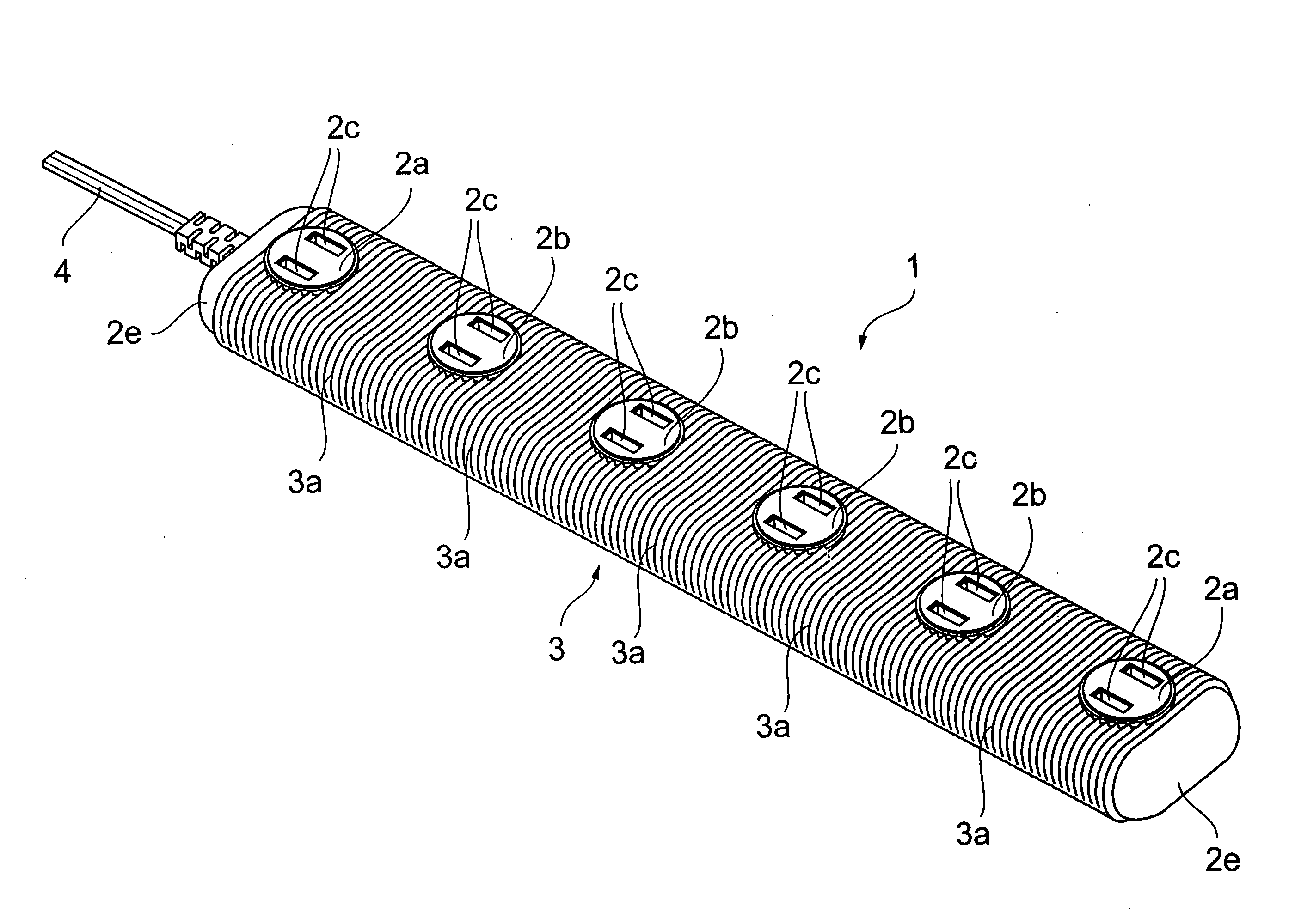
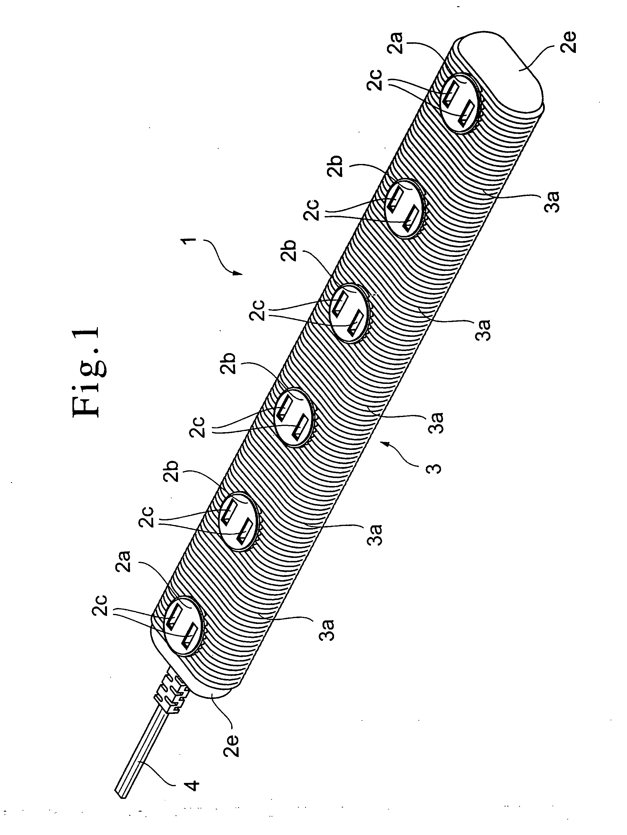
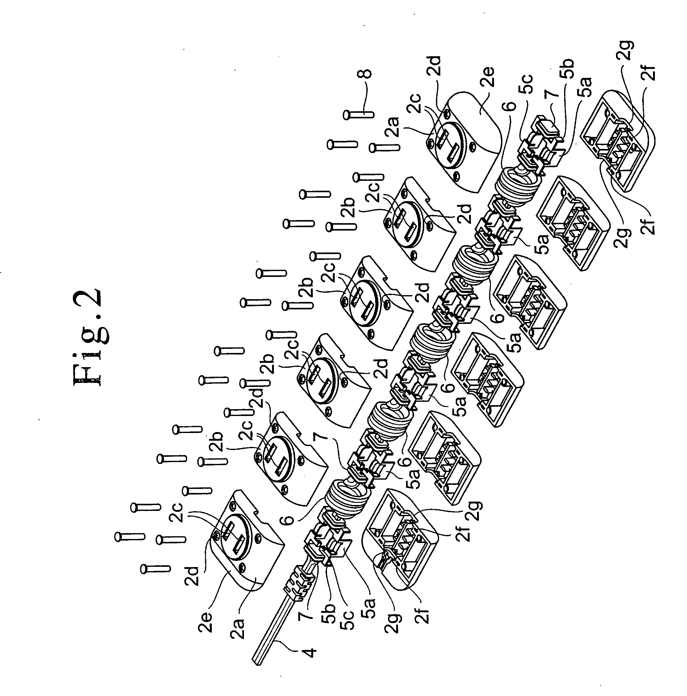
[0060] A power strip 1 that is a first embodiment of the invention is shown in FIGS. 1 to 9. FIG. 1 is an overview of the power strip 1. The power strip 1 has a socket 2a at either end and a number of sockets 2b (four in the illustrated power strip 1) spaced between the two sockets 2a. The total number of sockets 2a, 2b is therefore six. The sockets 2a, 2b are individually formed with pairs of terminal insertion holes 2c for insertion of the plugs of power cables connected with electrical devices, peripheral devices and the like and the terminals of AC adapters. The sockets 2a, 2b of the power strip 1 are located so that the sets of terminal insertion holes 2c formed at the sockets 2a, 2b are located along an imaginary straight line.

[0061] The regions surrounding of the sockets 2a, 2b are covered by a tubular cover 3 imparted with flexibility by formation of numerous corrugations 3a. This provides the power strip 1 with a structure that enables the cover 3 to flex at least along th...

second embodiment

[0079] A power strip 11 that is a second embodiment of the invention is shown in FIGS. 10 and 11. Elements of the second embodiment that are the same as those of the first embodiment are assigned the same reference symbols as their counterparts in the first embodiment and will not be explained again here. As shown in FIG. 11, the power strip 11 comprises sockets 12a, 12b having the same structure as the sockets 2a, 2b of the power strip 1. The end faces of the sockets 12a, 12b are formed with annular projections 12k and tubular joints 13 formed with corrugations 13a are fit on the outer peripheral surfaces of the annular projections 12k so as to interconnect the sockets 12a, 12b as shown in FIG. 10. The engagement strength between the annular projections 12k of the sockets 12a, 12b and the joints 13 can be increased by bonding the members with an adhesive. It is also possible to form at least the end regions of the joints 13 of an elastic material (e.g., rubber) for elastic engageme...

third embodiment

[0084] A power strip 21 that is a third embodiment of the invention is shown in FIGS. 12 to 14. FIG. 12 is an overview of the power strip 21. The power strip 12 has a socket 22a at either end and a number of sockets 22b (four in the illustrated power strip 21) spaced between the two sockets 22a. The edge faces of the sockets 22a, 22b are formed with pairs of terminal insertion holes 22c for insertion of plugs. The regions surrounding of the sockets 22a, 22b are covered by a tubular cover 23 imparted with flexibility by formation of numerous corrugations 23a. The tubular cover 23 is given a rectangular tubular shape matched to the profile of the sockets 22a, 22b. A power cable 24 extends outward from the socket 22a at one end of the power strip 21. The extremity of the power cable 24 is equipped with a plug for insertion into a wall socket, for example. The power strip 21 is equipped with switches 29 associated with the individual sockets 22a, 22b.

[0085] The internal structure of th...


PUM


Abstract

A power strip includes two or more spaced-apart sockets each having a set of terminal insertion holes for insertion of plug terminals of a power cable or the like and either at least one flexible joint that interconnects adjacent sockets or a flexible cover of substantially tubular shape that substantially covers and interconnects the sockets. The interconnection of the sockets by the flexible joints or the flexible cover. enables the spaces between adjacent sockets to be optimized for the types and numbers of plugs, AC adapters and the like to plugged into the sockets

Description

BACKGROUND OF THE INVENTION [0001] 1. Field of the Invention [0002] The present invention relates a power strip for supplying commercial AC power to any of number of electrical devices such as a personal computer, television set or audio device, particularly to a power strip provided with multiple sockets whose spacing and positional relationship can be modified. [0003] 2. Description of Related Art [0004] Power strips are used, for example, when the number of available wall sockets is insufficient or when the electrical device to be supplied with power is located at a distance from the wall socket. The power strip is particularly useful for personal computer users, who often simultaneously need to use a number of independently powered peripheral devices such as a printer, modem, hub, digital camera and the like. Such peripheral devices generally need to be supplied with electricity from an outlet that is near the computer unit. Use of a power strip having numerous sockets may becom...

Claims


Application Information

Patent Timeline
Patent Type & Authority Applications(United States)
IPC IPC(8): H01R25/00H01R13/46H01R13/514H01R13/518H01R35/00
CPCH01R35/00H01R25/003
Inventor TANAKA, HIROAKI
Owner TANAKA HIROAKI
Why Eureka
Try Eureka