Antenna selection diversity apparatus and receiving method

a technology of antenna selection and diversity, applied in the field of antenna selection diversity apparatus and reception method, can solve the problems of fluctuation of the level of the received signal, and achieve the effects of shortening the antenna selection diversity, shortening the antenna measurement time, and shortening the tim

Inactive Publication Date: 2006-10-19
PANASONIC CORP
View PDF3 Cites 24 Cited by
  • Summary
  • Abstract
  • Description
  • Claims
  • Application Information

AI Technical Summary

Benefits of technology

[0018] In accordance with the present invention, when antennas are switched in frame units, it is possible to shorten an antenna measuring time and shorten the time for selecting an optimal antenna from among a plurality of antennas on standby, and thereby realize antenna selection diversity even when a non-TDMA communication scheme is used.

Problems solved by technology

A mobile communication is often subject to fading which causes the level of a received signal to fluctuate depending on various radio wave propagation environments.

Method used


Image

  • Antenna selection diversity apparatus and receiving method
  • Antenna selection diversity apparatus and receiving method
  • Antenna selection diversity apparatus and receiving method

Examples


embodiment 1

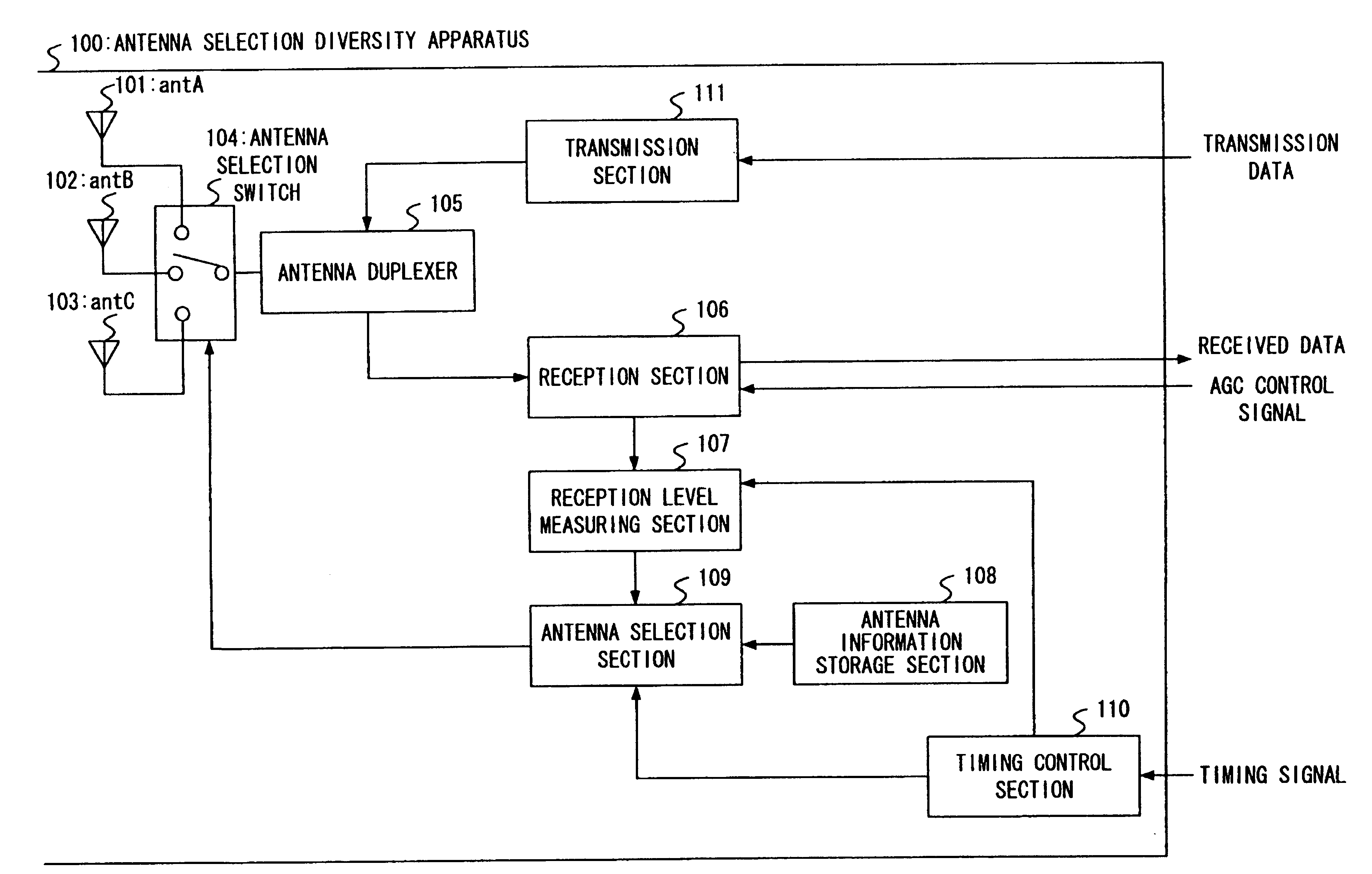
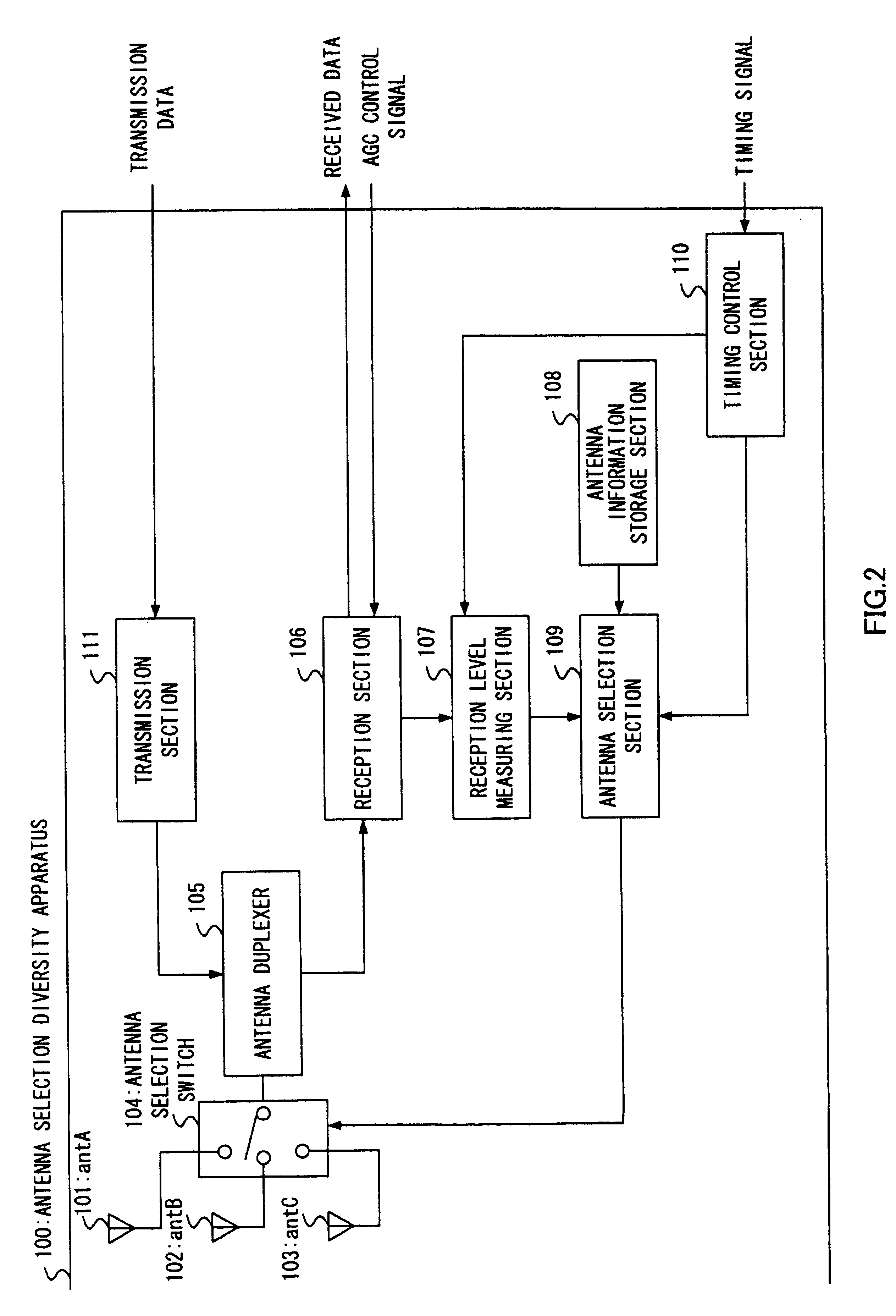
[0030]FIG. 2 is a block diagram showing the configuration of an antenna selection diversity apparatus according to Embodiment 1 of the present invention. The antenna selection diversity apparatus 100 shown in FIG. 2 is provided with an antenna 101 (hereinafter referred to as “antA”), an antenna 102 (hereinafter referred to as “antB”) and an antenna 103 (hereinafter referred to as “antC”), an antenna selection switch 104, an antenna duplexer 105, a reception section 106, a reception level measuring section 107, an antenna information storage section 108, an antenna selection section 109, a timing control section 110 and a transmission section 111. Here, amplifiers and filters, etc., are omitted.

[0031] In this embodiment, any one of antA, antB and antC becomes an antenna in actual use and the remaining two become antennas on standby. One of the two antennas on standby becomes an antenna to be measured whose reception level is compared with that of the antenna in actual use. This rela...

embodiment 2

[0043]FIG. 4 is a block diagram showing the configuration of an antenna selection diversity apparatus 300 according to Embodiment 2 of the present invention. In FIG. 4, components identical or equivalent to those shown in FIG. 2 (Embodiment 1) are assigned the same reference numerals. Here, mainly parts related to this Embodiment 2 will be explained.

[0044] As shown in FIG. 4, in this Embodiment 2, the configuration shown in FIG. 2 is provided with an antenna selection section 301 instead of the antenna selection section 109 and a level averaging section 302 provided between the reception level measuring section 107 and antenna selection section 301.

[0045] As in the case of Embodiment 1, the reception level measuring section 107 measures the reception levels of an antenna in actual use and an antenna to be measured once every 10 frames, but in Embodiment 2, both measurement results of the reception level measuring section 107 are input to the level averaging section 302.

[0046] The...

embodiment 3

[0053]FIG. 6 is a block diagram showing the configuration of an antenna selection diversity apparatus 500 according to Embodiment 3 the present invention. In FIG. 6, components identical or equivalent to those shown in FIG. 4 (Embodiment 2) are assigned the same reference numerals. Here, mainly parts related to this Embodiment 3 will be explained.

[0054] As shown in FIG. 6, in this Embodiment 3, an AGC voltage monitoring section 501 and antenna-in-actual-use level calculation section 502 are added to the configuration shown in FIG. 4 (Embodiment 2) and a timing control section 503 is provided instead of the timing control section 110.

[0055] The timing control section 503 gives an instruction for selecting an antenna to be measured to the antenna selection section 301 every plurality of frames, but the timing control section 503 does not give any instruction for measurement of the reception level of the antenna in actual use and gives only an instruction for measurement of the recep...


PUM


Abstract

An antenna selection diversity apparatus capable of shortening, when antennas are switched in frame units, a measuring time of antennas and shortening the time of selecting an optimal antenna from among a plurality of antennas on standby. In this apparatus, an antenna selection section (109) selects one of three antennas as an antenna in actual use for a period of a plurality of frames consecutively according to selection priority stored in an antenna information storage section (108) and gives an instruction for selecting one of two antennas on standby as an antenna to be measured once at a period of a plurality of frames to an antenna selection switch (104). When the reception level of the antenna in actual use measured by a reception level measuring section (107) falls below the reception level of the antenna to be measured a predetermined number of times consecutively, the antenna selection section (109) gives an instruction for selecting the antenna to be measured as the antenna in actual use to the antenna selection switch (104).

Description

TECHNICAL FIELD [0001] The present invention relates to an antenna selection diversity apparatus and reception method used for a mobile station such as a cellular phone and a base station which carries out radio communication with this mobile station in a mobile communication system. BACKGROUND ART [0002] A mobile communication is often subject to fading which causes the level of a received signal to fluctuate depending on various radio wave propagation environments. An effective measure against this fading is antenna selection diversity. The antenna selection diversity is implemented normally by installing a plurality of antennas and carrying out communication by selecting an antenna with good conditions when a reception condition deteriorates due to fading. As such an antenna selection diversity apparatus, for example, those disclosed in Patent Documents 1 and 2 are conventionally known. [0003] Patent Documents 1 and 2 disclose antenna selection diversity apparatuses based on a TD...

Claims


Application Information

Patent Timeline
Patent Type & Authority Applications(United States)
IPC IPC(8): H04B1/02H04M1/00H04B7/02H04B7/08H04B7/26
CPCH04B7/0874H04B7/08
Inventor ISHIHARA, YOSHIHARUIWATA, YASUSHIOBARA, TOSHIO
Owner PANASONIC CORP
Why Eureka
Try Eureka