Wire-like structure torsion angle calculating method, and device and program therefor

Active Publication Date: 2006-10-19
YAZAKI CORP
View PDF6 Cites 13 Cited by
  • Summary
  • Abstract
  • Description
  • Claims
  • Application Information

AI Technical Summary

Benefits of technology

[0061] According to the inventions set forth in claims 14, 16, and 17, a main wire member deformed shape model is produced in which a deformed shape of a main wire member is expressed as a coupled member of a plurality of beam elements, and a branch axis for obtaining a twist angle of a sub wire member is added to a wire member branch node on the main wire member, and a main wire member reference shape model is produced in which the main wire member is expressed as a coupled member of a plurality of beam elements so as to correspond to a main wire member reference shape that is a shape obtained by straightly stretching the main wire member without being twisted, and a first reference axis which functions as a reference for obtaining a twist angle of the branch axis is added to a position corresponding to the wire member branch node. Next, a first twist angle which is an angle formed by the first reference axis and the branch axis when the main wire member reference shape model is deformed and then superimposed on the main wire member deformed shape model is calculated with using a finite element method. A sub wire member deformed shape model is produced in which a deformed shape of the sub wire member is expressed as a coupled member of a plurality of beam elements, and a clamp axis for obtaining a twist angle of a clamp is added to a clamp attachment node on the sub wire member, and a sub wire member reference shape model is produced in which the sub wire member is expressed as a coupled member of a plurality of beam elements so as to correspond to a sub wire member reference shape that is a shape obtained by straightly stretching the sub wire member without being twisted, and a second reference axis which functions as a reference for obtaining a twist angle of the clamp axis is added to a position corresponding to the clamp axis. Next, a second twist angle that is an angle which is formed by the second reference axis and the clamp axis when the sub wire member reference shape model is deformed and then superimposed on the sub wire member deformed shape model is calculated with using a finite element method. The second twist angle is corrected on the basis of the first twist angle, and an angle formed by the first reference axis and the clamp axis is obtained. Therefore, it is possible to correctly calculate a twist angle of a clamp attached to a sub wire member that branches off from a main wire member, as viewed from a side of the main wire member.
[0062] According to the invention set forth in claim 15, a main wire member deformed shape model is produced in which a deformed shape of a main wire member is expressed as a coupled member of a plurality of beam elements, and a first branch axis for obtaining a twist angle of a sub wire member is added to a wire member branch node on the main wire member, and a main wire member reference shape model is produced in which the main wire member is expressed as a coupled member of a plurality of beam elements so as to correspond to a main wire member reference shape that is a shape obtained by straightly stretching the main wire member without being twisted, and a first reference axis which functions as a reference for obtaining a twist angle of a first branch axis is added to a position corresponding to the wire member branch node. Next, a first twist angle that is an angle which is formed by the first reference axis and the first branch axis when the main wire member reference shape model is deformed and then superimposed on the main wire member deformed shape model is calculated with using a finite element method. Furthermore, a sub wire member deformed shape model is produced in which a deformed shape of the sub wire member is expressed as a coupled member of a plurality of beam elements, and a second branch axis for obtaining a twist angle of a second sub wire member is added to a second wire member branch node on the sub wire member, and a sub wire member reference shape model is produced in which the sub wire member is expressed as a coupled member of a plurality of beam elements so as to correspond to a sub wire member reference shape that is a shape obtained by straightly stretching the sub wire member without being twisted, and a second reference axis which functions as a reference for obtaining a twist angle of the second branch axis is added to a position corresponding to the second wire member branch node. Next, a second tw

Problems solved by technology

It has been considered that it is difficult to correctly obtain a twist angle in such a wire harness.
Therefore, an effective technique

Method used


Image

  • Wire-like structure torsion angle calculating method, and device and program therefor
  • Wire-like structure torsion angle calculating method, and device and program therefor
  • Wire-like structure torsion angle calculating method, and device and program therefor

Examples


first embodiment

[0209] [First Embodiment]

[0210]FIG. 10 is a flowchart showing a process procedure in the first embodiment of the invention, and FIGS. 11(A) to 11(C) are flowcharts respectively showing subroutines in the process procedure of FIG. 10. FIGS. 12(A) to 12(E) are views exemplarily showing states in the process of FIG. 10, and FIG. 13 is a view illustrating the process of FIG. 11(C). The objective wire harness may be a wire harness which has no branch, and to which a clamp(s) is attached, one which has a branch(es), and to which no clamp is attached, or one which has a branch(es), and to which a clamp(s) is attached. FIG. 12 shows, as a typical example, a wire harness which has no branch, and to which clamps are attached.

[0211] First, in step S1 of FIG. 10, a deformed shape is designed, and the designed deformed shape is output to the display device 43. The deformed shape is a wire harness 1′ the shape of which is designed as shown in FIG. 12(A) so that the wire harness is laid in a pred...

second embodiment

[0225] [Second Embodiment]

[0226]FIG. 14 is a flowchart showing a process procedure in a second embodiment of the invention. FIGS. 15(A) to 15(D) are views exemplarily showing states in the process of FIG. 14, respectively.

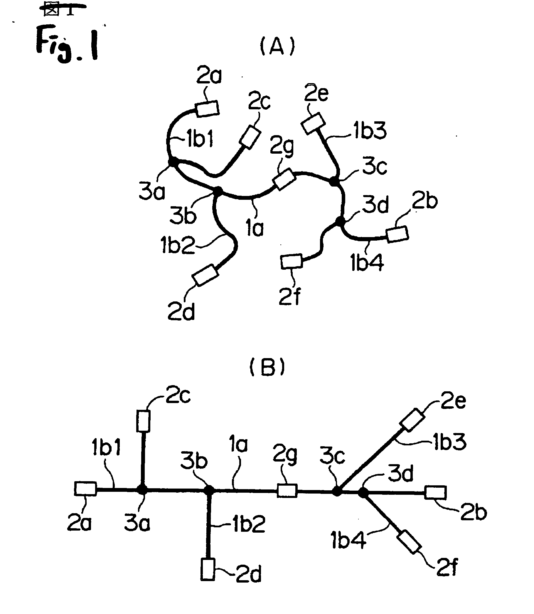
[0227] First, in step S201 of FIG. 14, a deformed shape such as shown in FIG. 15(A) is designed in the same manner as step S1 of FIG. 10, and the designed deformed shape is output to the display device 43. In the embodiment, a wire harness 1″ is assumed which includes a trunk wire 11a and branch wires 11b1 to 11b5 that branch off from the trunk wire 11a. It is a matter of course that, in the same manner as the first embodiment, a clamp may be attached to an intermediate portion of the trunk wire 11a. For example, the wire harness 1″ includes the trunk wire 11a, and a plurality of branch wires 11b1 to 11b5 which branch off from the trunk wire 11a in different directions. Clamps 21a to 21g are attached to end portions of the trunk wire 11a and the branch wires 11b1 ...

third embodiment

[0238] [Third Embodiment]

[0239]FIG. 16 is a flowchart showing a process procedure in a third embodiment of the invention, and FIGS. 17 to 19 are views exemplarily showing states in the process of FIG. 16, respectively. The third embodiment is configured by expanding the concept of the first embodiment so as to, in a wire harness having a branch wire which branches off from a trunk wire, or that in which a clamp is further attached to a branch wire, obtain twist angles of the branch wire and the clamp.

[0240] First, in step S301 of FIG. 16, a deformed shape is designed, and the designed deformed shape is output to the display device 43. The deformed shape 100B is a wire harness 100 the shape of which is designed as shown in FIG. 17 so that the wire harness is laid in a predetermined portion such as a door of a vehicle or a floor. For example, the wire harness 100 includes: a trunk wire 100a; branch wires 100b1, 100b2, 100b3 which branch off from the trunk wire 100a; and clamps 200a t...


PUM


Abstract

A method which can correctly calculate a twist angle in a wire harness, an apparatus for the method, and a program for the method are provided. In the invention, a shape obtained by deforming a reference shape model and superimposing the deformed reference shape model on a deformed shape model is calculated with using a finite element method, while referring physical properties of a wire-like structure. In accordance with the superimposition, also a reference axis of the reference shape model is rotated. An angle formed by the reference axis at the timing when the superimposition is ended, and a clamp axis of the deformed shape model and/or a virtual clamp axis is calculated as a twist angle.

Description

TECHNICAL FIELDS [0001] The present invention relates to a method of, with using a computer, calculating a twist angle of a wire member and / or a clamp which is produced when a wire-like structure is deformed to a predetermined shape, the wire-like structure including: a main wire member; a sub wire member that branches off from the main wire member; and / or the clamp that is attached to the main wire member, and also to an apparatus for the method, and a program for the method. BACKGROUND ART [0002] Recently, various electrical components are mounted on a vehicle or the like. Such electrical components are connected by a wire-like structure called a wire harness in which a plurality of electric wires or communication lines are bundled by a bundling member such as an insulation lock or a protective member such as a tape. Such a wire harness is designed so as to be laid in a predetermined three-dimensional space, and produced while being developed two-dimensionally on a jig plate. [000...

Claims


Application Information

Patent Timeline
IPC IPC(8): G01C19/00G06F17/50H01B13/00H01B13/012H02G3/00H02G3/38
CPCG06F17/5018B60R16/0207G06F2217/36G06F30/23G06F2113/16
Inventor SAWAI, MASAYOSHINAKANO, AKIKO
Owner YAZAKI CORP
Why Eureka
Try Eureka