Suction brush assembly having ultrasonic oscillator and a vacuum cleaner having the same

Inactive Publication Date: 2006-10-26
SAMSUNG GWANGJU ELECTRONICS CO LTD
View PDF0 Cites 25 Cited by
  • Summary
  • Abstract
  • Description
  • Claims
  • Application Information

AI Technical Summary

Benefits of technology

[0006] Accordingly, an aspect of the present invention is to provide a vacuum cleaner including a suction port assem

Problems solved by technology

However, the bristle member can not easily separate the dust when the dust is firmly attached on the surface being cleaned.
However, the bristle member i

Method used


Image

  • Suction brush assembly having ultrasonic oscillator and a vacuum cleaner having the same
  • Suction brush assembly having ultrasonic oscillator and a vacuum cleaner having the same
  • Suction brush assembly having ultrasonic oscillator and a vacuum cleaner having the same

Examples


Embodiment Construction

[0017] Hereinafter, certain embodiments of the present invention will be described in detail with reference to the accompanying drawing figures. The matters defined in the description, such as a detailed construction and elements, are provided only to assist in a comprehensive understanding of the invention. Thus, it is apparent that the present invention can be carried out without those defined matters. Also, well-known functions or constructions are not described in detail.

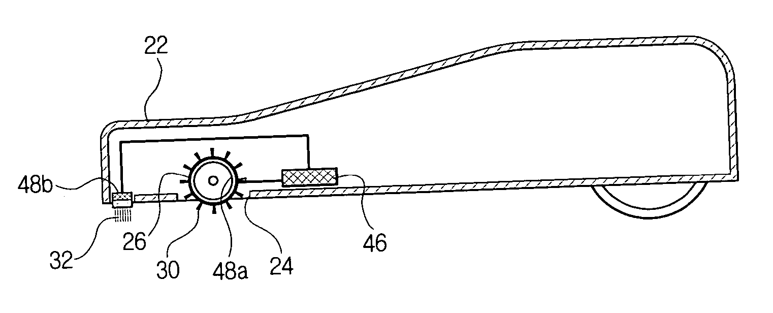
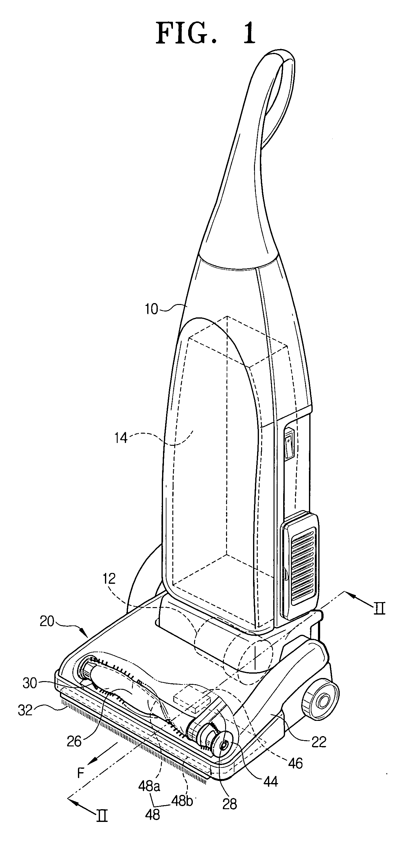
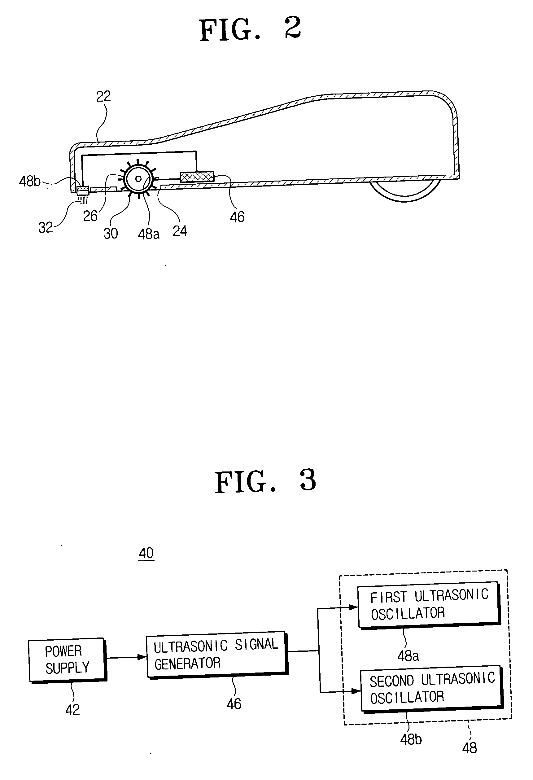
[0018] Referring to FIGS. 1 to 4, a vacuum cleaner according to an embodiment of the present invention comprises a cleaner body 10 and a suction port assembly 20 in fluid communication with a lower part of the cleaner body 10. The cleaner body 10 comprises a driving source 12 for generating a suction force at a lower part therein and a dust collecting chamber 14 for storing dust drawn in by the suction force generated by the driving source 12.

[0019] The suction port assembly 20 comprises a housing 22, a rotary...


PUM


Abstract

A suction port assembly for a vacuum cleaner, that includes a housing that has a suction port, and a rotary drum rotatably mounted on the housing. The rotary drum has a first bristle member on its outer circumference, which is adapted to contact a surface to be cleaned. An ultrasonic generation unit vibrates the first bristle member.

Description

CROSS-REFERENCE TO RELATED APPLICATION [0001] This application claims benefit under 35 U.S.C. § 119(a) of Korean Patent Application No. 2005-33719, filed Apr. 22, 2005, the entire contents of which are incorporated herein by reference. FIELD OF THE INVENTION [0002] The present invention relates to a vacuum cleaner. More particularly, the present invention relates to a vacuum cleaner including a suction brush assembly having an ultrasonic oscillator. BACKGROUND OF THE INVENTION [0003] Vacuum cleaners generally comprise a cleaner body including a suction motor which generates a suction force, and a suction port assembly pivotably mounted to a lower part of the cleaner body by a predetermined angle. Dust is drawn in from the surface being cleaned by the suction force of the suction motor. [0004] The suction port assembly comprises a housing having a suction port, and a rotary drum pivotably coupled to the housing. The rotary drum has a bristle member which contacts the surface being cl...

Claims


Application Information

Patent Timeline
IPC IPC(8): A47L9/06A47L5/30
CPCA47L9/0411A47L9/0488A47L9/0483A47L9/0477A47L9/02A47L9/04
Inventor OH, JANG-KEUNLEE, HAK-BONG
Owner SAMSUNG GWANGJU ELECTRONICS CO LTD
Why Eureka
Try Eureka