Hinge

Inactive Publication Date: 2006-10-26
SHIN ZU SHING
View PDF10 Cites 18 Cited by
  • Summary
  • Abstract
  • Description
  • Claims
  • Application Information

AI Technical Summary

Benefits of technology

[0007] The main objective of the present invention is to provide a hinge that provides uniform friction. The hinge has a sleeve and a shaft and is mounted between a cover and a base of an electrical device. The sleeve is hollow, is attached to the base and has an internal diameter. The shaft is attached to the 24 cover, is mounted pivotally in the sleeve and has a hollow torsion rod. The torsion rod has an external diameter, an opening e

Problems solved by technology

However, a non-circular torsion rod (61) has non-uniform friction with the sleeve (50).
The non-uniform friction causes the torsion rod (61) wear unevenly and the torsion rod (61) is damaged quickly.
The separate rubbing causes additional non-uniform friction.

Method used


Image

  • Hinge
  • Hinge
  • Hinge

Examples


Embodiment Construction

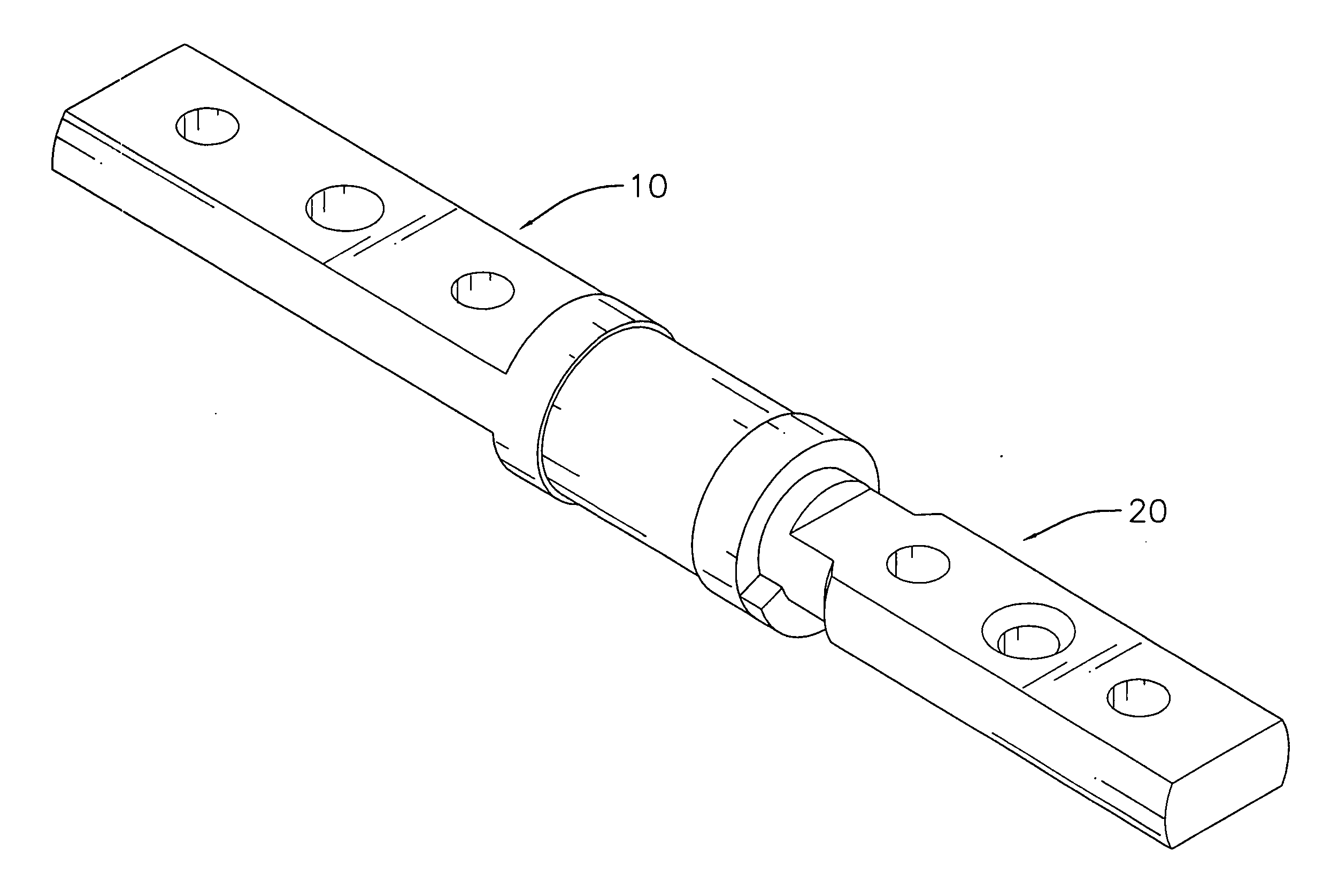
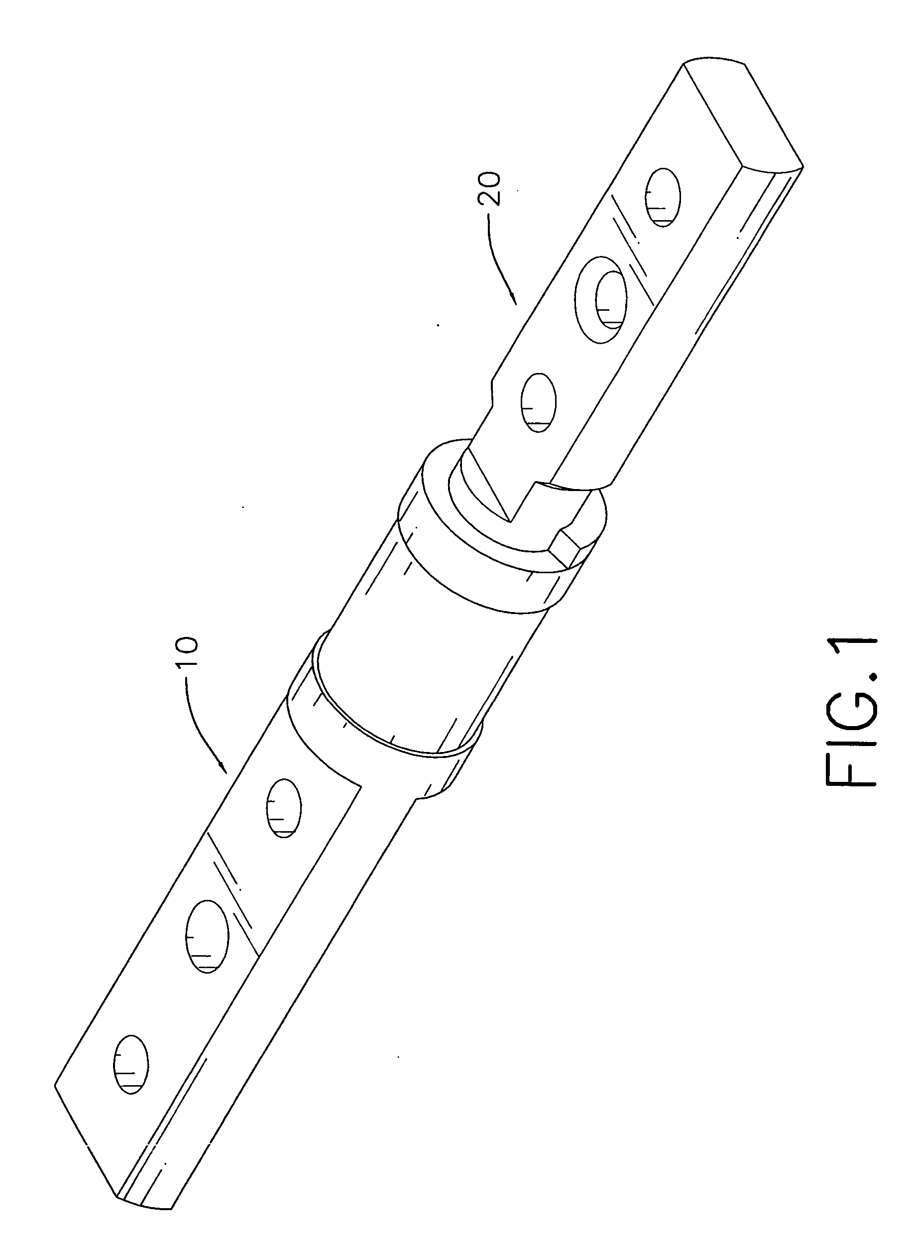
[0016] With reference to FIGS. 1 and 2, a hinge in accordance with the present invention comprises a sleeve (10) and shaft (20).

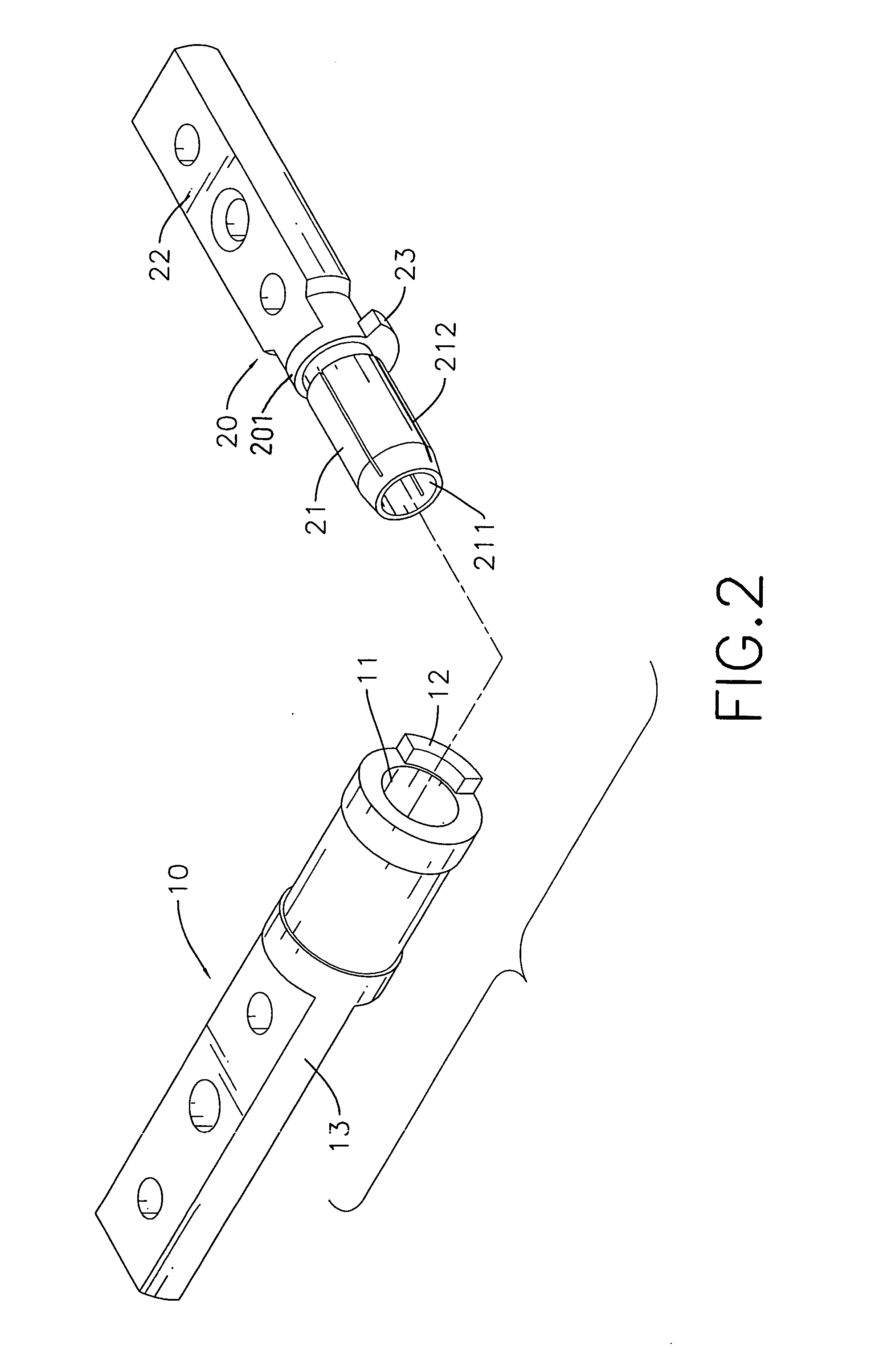
[0017] The sleeve (10) is hollow and has an internal diameter, an opening end (11), a close end, a limit (12) and a leaf (13). The limit (12) is formed axially on the opening end (11) and has two ends. The leaf (13) is formed on the close end.

[0018] The shaft (20) is mounted rotatably in the sleeve (10) and has a head (201), a stop (23), a torsion rod (21) and a leaf (22). The head (201) abuts the opening end (11) of the sleeve (10) and has an edge, a proximal side and a distal side. With further reference to FIGS. 4 and 5, the stop (23) is formed radially on the edge of the head (201) and selectively abuts against the two ends of the limit (12) on the sleeve (10) to limit the rotating angle of the shaft (20). The torsion rod (21) is hollow, is formed axially on the proximal side of the head (201) and has an external diameter, an outer wall, an opening en...


PUM


Abstract

A hinge has a sleeve and a shaft and is mounted between a cover and a base of an electrical device. The sleeve is hollow, is attached to the base and has an internal diameter. The shaft is attached to the cover, is mounted pivotally in the sleeve and has a hollow torsion rod. The torsion rod has an external diameter, an opening end and multiple slots. The external diameter of the torsion rod is bigger than the internal diameter of the sleeve to provide friction. The slots are formed in the torsion rod without communicating with the opening end to provide uniform friction. Because the torsion rod is hollow to provide spaces for the torsion rod to be deformed, the torsion rod maintains its shape. Therefore the torsion rod provides uniform friction with the sleeve.

Description

BACKGROUND OF THE INVENTION [0001] 1. Field of the Invention [0002] The present invention relates to a hinge, especially to a hinge mounted in an electrical appliance to allow a cover to pivot relative to a base. [0003] 2. Description of the Prior Arts [0004] Electrical devices such as notebook computers, cellular phones, etc. comprise a cover, a base and a hinge. The hinge is mounted between the cover and the base to allow the cover to pivot relative to the base. Conventional hinges are available in many types. With reference to FIGS. 6 and 7, one type of conventional hinges comprises a sleeve (50) and a shaft (60). The sleeve (50) has an internal diameter, an opening end (51), a closed end, a limit (52) and a leaf (53). The limit (52) is formed longitudinally on the opening end (51). The leaf (53) is formed on and protrudes longitudinally from the closed end and attaches to a base of an electrical device. The shaft (60) is mounted rotatably in the sleeve (50) and has a head, a tor...

Claims


Application Information

Patent Timeline
IPC IPC(8): E05D11/08G06F1/16H05K7/16
CPCE05D11/082E05Y2900/606Y10T16/54038G06F1/1681G06F1/1616E05Y2999/00
Inventor LU, SHENG-NANWANG, TING-HSIEN
Owner SHIN ZU SHING
Why Eureka
Try Eureka