Self-cleaning trigger connector system

a technology of trigger connectors and self-cleaning, which is applied in the field of self-cleaning firearm trigger stop mechanisms, can solve the problems of existing system lock-up and fail to function, serious injury or death, and reduce accuracy and precision when firing, so as to reduce accuracy, prevent over-manipulation, and increase the speed of firing a firearm

Inactive Publication Date: 2006-10-26
VIANI ARTHUR
View PDF6 Cites 14 Cited by
  • Summary
  • Abstract
  • Description
  • Claims
  • Application Information

AI Technical Summary

Benefits of technology

[0022] It is another object of the present invention to incorporate a self-cleaning trigger connector system for firearms to prevent over manipulation of the trigger, which causes a reduction of accuracy while repetitive firing.
[0023] It is yet another object of this invention to increase the speed of firing a firearm with a reduced trigger travel distance.

Problems solved by technology

While the existing trigger connectors are adequate for functioning under ideal conditions in the absence of fouling, environmental substances or debris the presence of these things causes the existing system to lock up and fail to function.
The failure of the existing system during target practice maybe annoying but would not be life threatening, if the trigger system fails during a self defense incident the outcome could be catastrophic resulting in serious injury or a loss of a life.
This generally downward and sideward path of the barrel after the initial discharge of the firearm, caused by the user exerting force beyond the point of firing, results in a reduction of accuracy and precision when firing.
However, this remedy is not precise and generally leaves an unfinished appearance to the firearm.

Method used


Image

  • Self-cleaning trigger connector system
  • Self-cleaning trigger connector system
  • Self-cleaning trigger connector system

Examples


Embodiment Construction

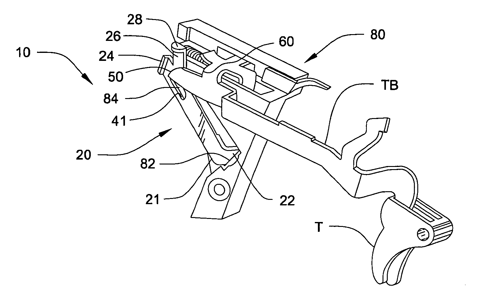
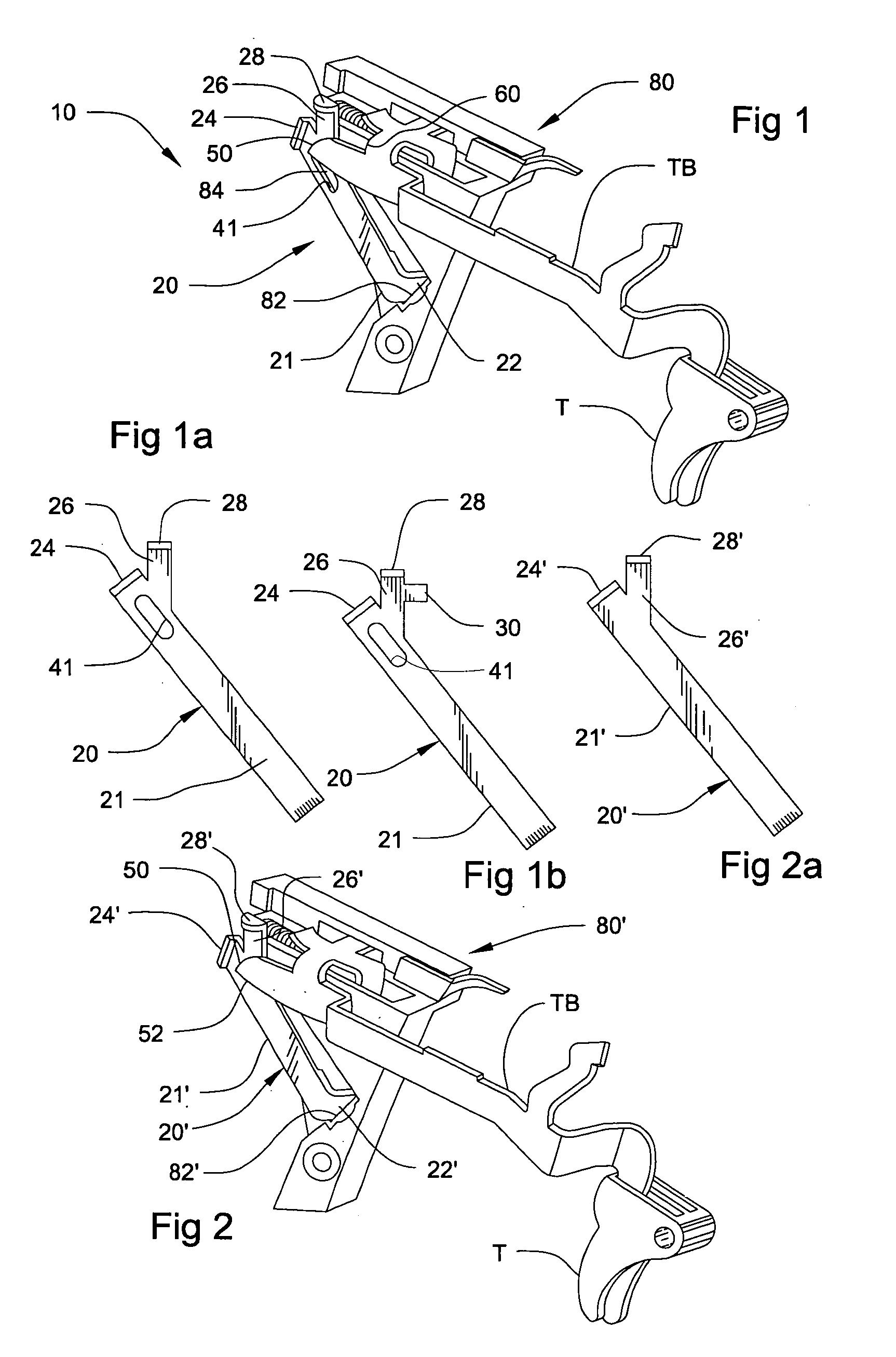
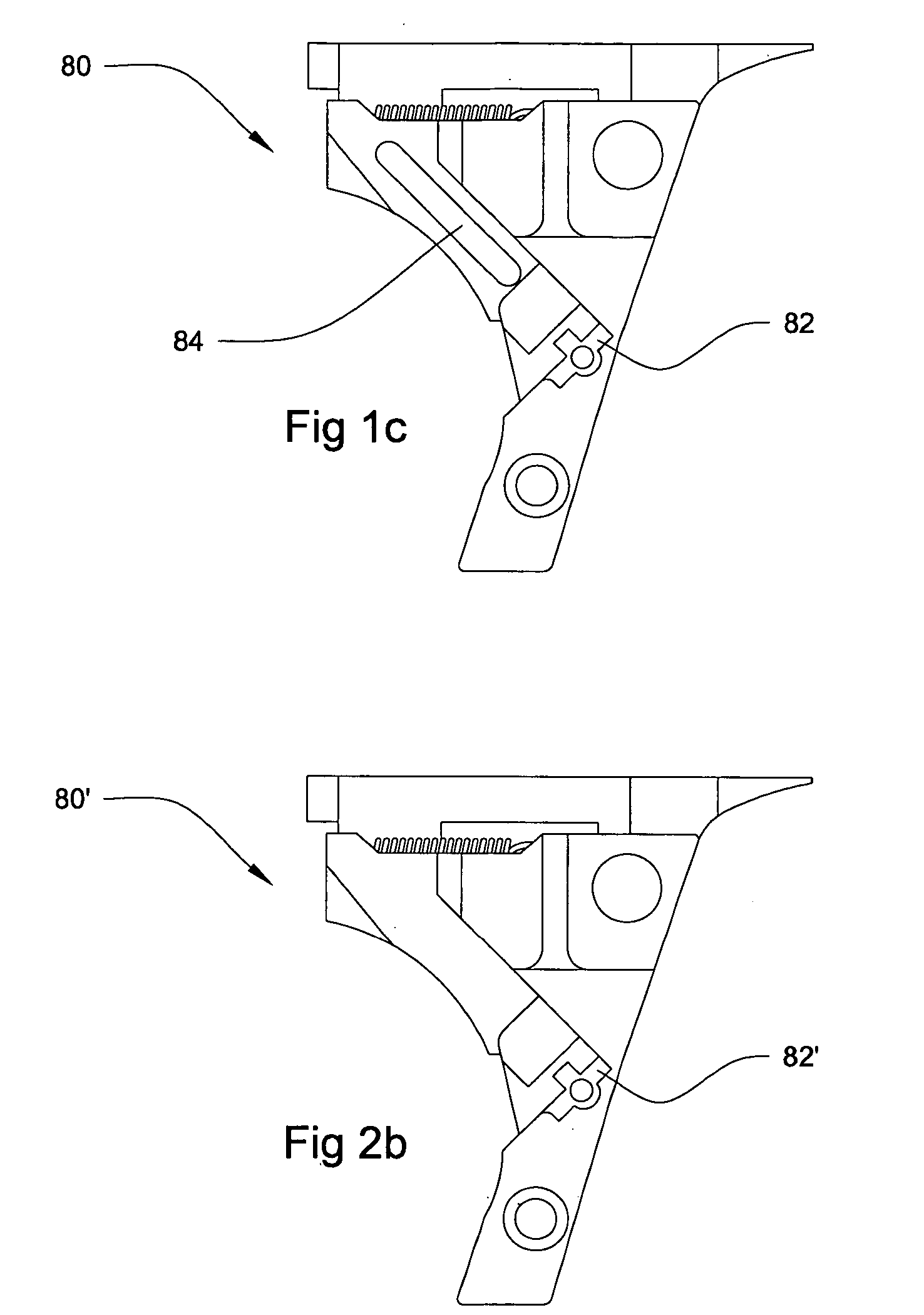
[0037] Referring now to the drawings, where the present invention is generally referred to with numeral 10, it can be observed that it basically includes self-cleaning trigger connector 20, bent at predetermined locations to permit its mechanical transactions to effectuate a self-cleaning trigger connector mechanism, and trigger mechanism housing 80. Instant invention 10 is made out of a durable and lightweight material as stainless steel, alloy metal, or other material having similar characteristics. In the preferred embodiment, self-cleaning trigger connector 20 is manufactured as a single metallic piece and has a general consistent thickness throughout of approximately 0.65 mm to 1.25 mm, so as to cooperatively interact with the general trigger mechanism of semiautomatic firearms that have an enclosed striker assembly. Such a firearm may be “GLOCK”, without limitation to this specific brand.

[0038] As seen in FIG. 1, self-cleaning trigger connector 20 and trigger mechanism housin...


PUM


Abstract

A self-cleaning trigger connector system resulting in increased reliability comprising a self-cleaning trigger connector and a trigger mechanism housing. The self-cleaning trigger connector is designed with specific contact points to prevent over-travel of the trigger bar when operating in cooperation with the trigger of the firearm. The self-cleaning trigger connector has a first at least one elongated through hole of a predetermined length that allows for a lighter trigger pull and defines a lubrication reservoir. The trigger mechanism housing comprises a second at least one elongated through hole. Debris that accumulates from the interaction between the trigger bar and the self-cleaning trigger connector passes through the first and second at least one elongated through holes. After passing through the first and second at least one elongated through holes, the debris then falls downwardly through a cavity adjacent to the firearm magazine well.

Description

BACKGROUND OF THE INVENTION [0001] 1. Field of the Invention [0002] The present invention relates to firearms, and more particularly, to a self-cleaning firearm trigger stop mechanism. [0003] 2. Description of the Related Art [0004] Firearms are mostly used utilized by military, law enforcement, sport enthusiasts, and private owners for target, game and self-defense. Firearms are fired by their trigger mechanisms, more specifically in various firearms trigger connectors are used to regulate and control the movement of triggers to fire firearms. There are many connector types with predetermined angles to control trigger poundage and movement. They may be used to control and regulate the triggers on various firearms. Presently connectors serve only one main purpose that of controlling trigger function. While the existing trigger connectors are adequate for functioning under ideal conditions in the absence of fouling, environmental substances or debris the presence of these things caus...

Claims


Application Information

Patent Timeline
Patent Type & Authority Applications(United States)
IPC IPC(8): F41A19/00
CPCF41A19/30
Inventor VIANI, ARTHUR
Owner VIANI ARTHUR
Why Eureka
Try Eureka