
Animal restraining apparatus

Inactive Publication Date: 2006-10-26
ABINANTI T MICHAEL
View PDF0 Cites 14 Cited by
  • Summary
  • Abstract
  • Description
  • Claims
  • Application Information

AI Technical Summary

Benefits of technology

[0007] It is one object of this invention to provide an animal restraining device that is less harmful to an animal being trained or exercised.
[0008] It is another object of this invention to provide an animal restraining device that prevents entanglement of a leash in an animal's leg.
[0015] Preferably but not necessarily, the line is overlapped near the keeper element. When overlapped, the opposite free end portions can be directed away from each other to close the belt and thus reduce the size of the opening. In one embodiment of this invention, the belt can be positioned about a stomach area or other body portion of the animal.
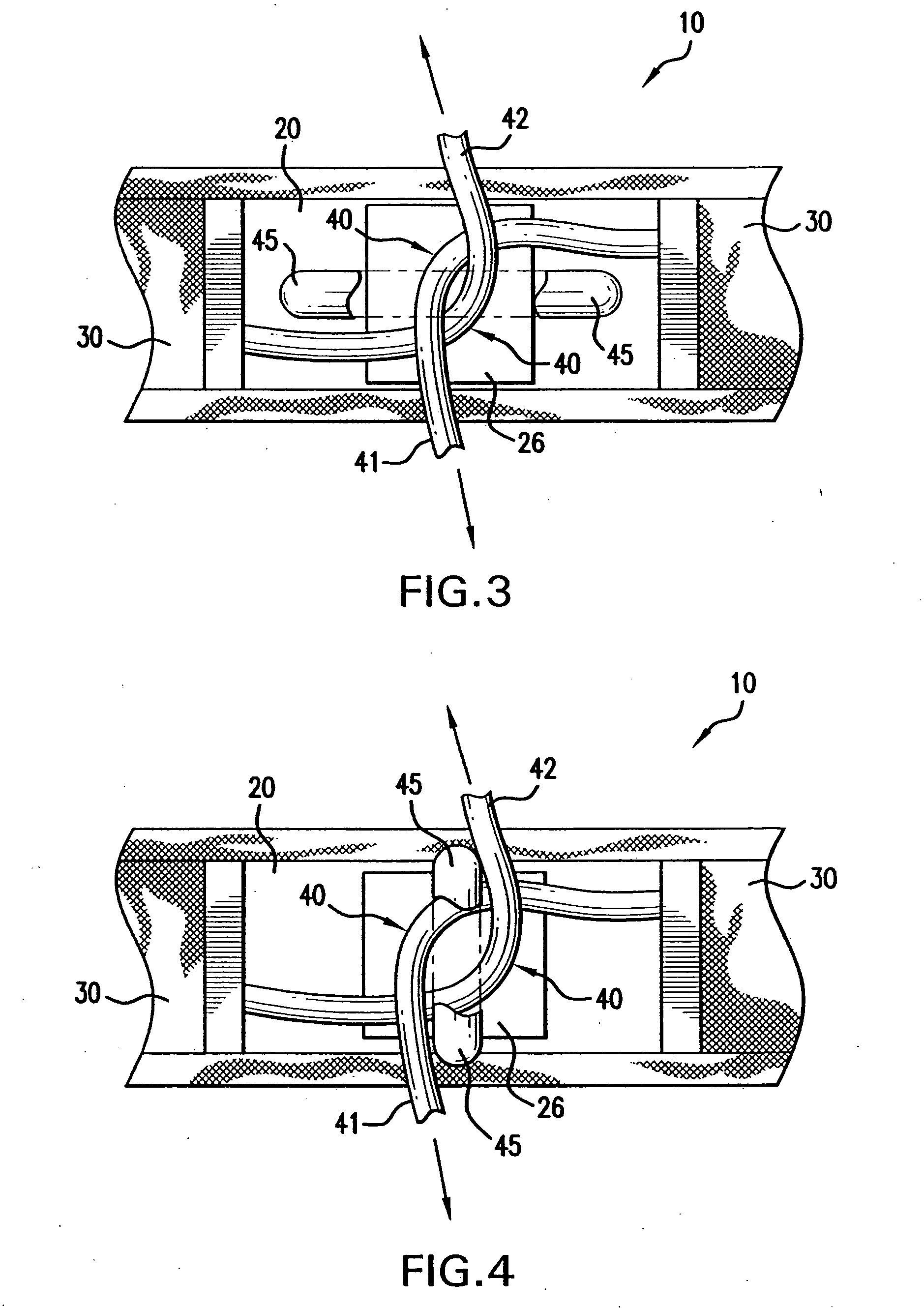
[0017] When the leash is pulled and the other free end portion is directed away from the belt, the length of the belt portion which is within the channel between the guide element and the belt decreases and thus reduces the size of the opening. The reduced opening size fits tighter around a stomach area of the animal and thus tightens the belt about the body of the animal.
[0018] When the force on the leash is released, the length of the belt portion within the channel increases and thus increases the size of the opening and relieves pressure on the body of the animal.
[0020] The animal restraining apparatus of this invention reduces undesirable forces applied to the neck area of the animal. The animal restraining apparatus of this invention reduces pulling forces applied to a collar. Also, the animal restraining apparatus of this invention prevents the leash from being tangled within the legs of the animal, for example when the animal is running with an unattended leash.

Problems solved by technology

However, many conventional collars choke or otherwise apply undesirable forces to a neck portion of the animal.

Method used


Image

  • Animal restraining apparatus
  • Animal restraining apparatus
  • Animal restraining apparatus

Examples


Embodiment Construction

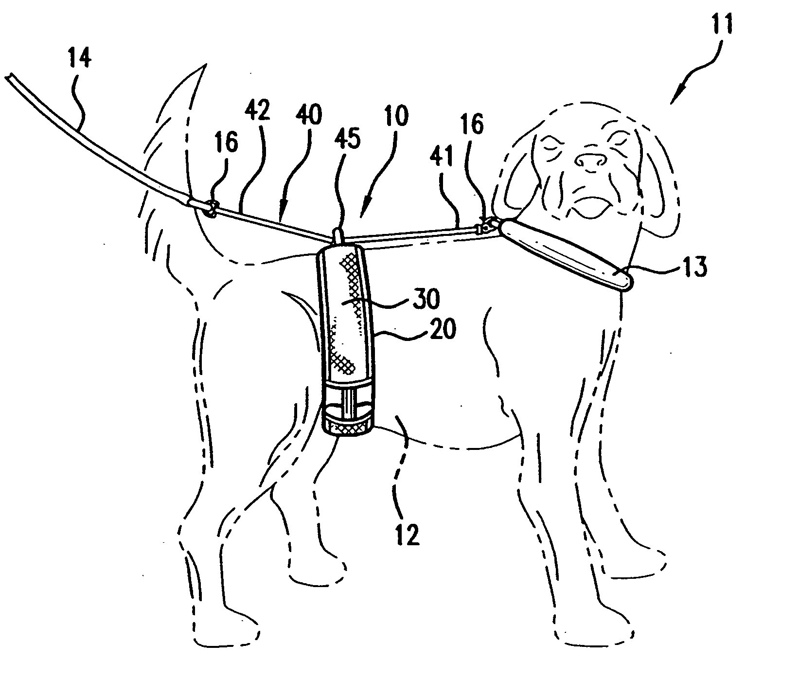
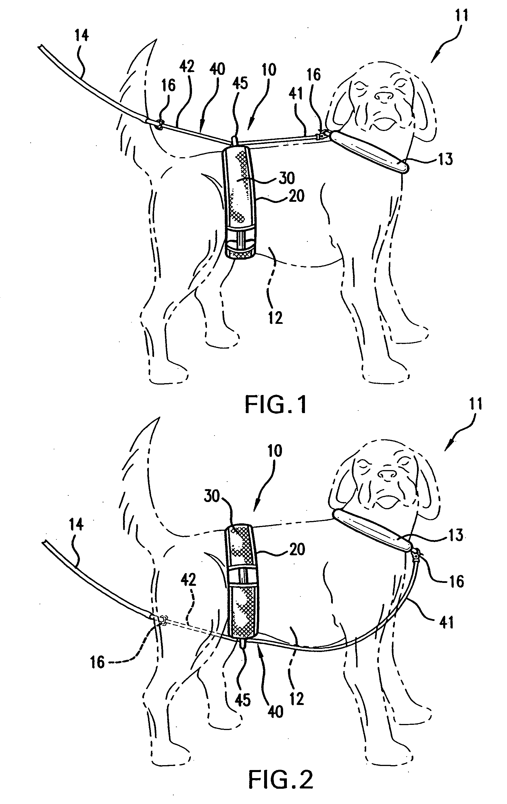
[0037]FIGS. 1 and 2 show animal restraining apparatus 10 positioned on animal 11, such as a dog, and acting as a cincture positioned about girth 12 of animal 11.

[0038]FIGS. 5, 7A, 7B and 8 show belt 20 forming a void or opening 22. FIGS. 1 and 2 show girth 12 of animal 11 positioned within opening 22. Opposing free end portions 41 and 42 of line 40 are pulled in opposite directions to reduce the size of opening 22, such as shown in FIG. 7B. As belt 20 tightens about girth 12 of animal 11, the constricting movement grabs the attention of and thus restrains animal 11.

[0039] Belt 20 can be positioned at various suitable locations along the body of animal 11. FIGS. 1 and 2 show one preferred position of belt 20 with respect to animal 11, where belt 20 is slightly forward of the front portion of the two rear legs of animal 11.

[0040]FIG. 1 shows belt 20 positioned so that keeper element 45 points upward. In this position, free end portion 42 of line 40 and / or leash 14 is routed over th...


PUM


Abstract

An animal restraining apparatus having a belt positionable about a girth of an animal. A collar is positionable about a neck portion of the animal. A strap connects the belt to the collar. An elastic element is connected with respect to the strap to gather a portion of the strap to form an undulation in the strap. The elastic element is extendable with respect to the strap to remove the undulation. A second elastic element can be connected with respect to the collar to gather a portion of the collar to form an undulation. The second elastic element is extendable with respect to the collar to remove the undulation in the collar. In one embodiment of this invention, a leash guard is removably attachable to the belt and has a guide ring. A leash can be guided through the guide ring and a belt ring mounted on the belt, and attached directly to the collar.

Description

CROSS REFERENCE TO RELATED APPLICATION [0001] This application is a continuation-in-part of U.S. application Ser. No. 10 / 902,501, filed on 29 Jul. 2004. The co-pending parent application is hereby incorporated by reference herein in its entirety and is made a part hereof, including but not limited to those portions which specifically appear hereinafter. BACKGROUND OF THE INVENTION [0002] 1. Field of the Invention [0003] This invention relates to an apparatus for restraining an animal, such as a dog, that can be used in combination with a collar. [0004] 2. Discussion of Related Art [0005] Many different conventional collars are used to restrain a dog or other household animal when training and / or exercising the animal. Conventional collars are adjustable, for example with a buckle, with a hook-and-loop strap or any other suitable adjustable fastener. Other conventional collars include a choke chain. [0006] During training or exercise, a leash is attached to the conventional collar. W...

Claims


Application Information

Patent Timeline
IPC IPC(8): A01K27/00
CPCA01K27/001A01K27/003A01K27/002
Inventor ABINANTI, T. MICHAEL
Owner ABINANTI T MICHAEL
Learn More