Bypass pressure regulator

a pressure regulator and bypass technology, applied in the direction of liquid fuel feeders, machines/engines, mechanical equipment, etc., can solve the problems of undesirable noise in the fuel system or other liquid system, high manufacturing cost of bypass pressure regulators, and affecting the performance of the engine, so as to achieve less noise, less prone to noise, and less expensive

Active Publication Date: 2006-10-26
WALBRO LLC
View PDF14 Cites 8 Cited by
  • Summary
  • Abstract
  • Description
  • Claims
  • Application Information

AI Technical Summary

Benefits of technology

[0012] Objects, feature, and advantages of this invention include a bypass pressure regulator which produces a more uniform regulated output pressure and flow rate, is relatively inexpensive and versatile, quieter and less prone to p...

Problems solved by technology

This is especially true when the engine is idling and has an extremely low fuel demand while the fuel pump is still delivering a large quantity.
Although generally satisfactory in performance, and beneficial for the ability to accommodate thermally expanding or excess fuel, these bypass pressure regulators are expensive to manufacture because of the diaphragm and numerous parts.
Furthermore, the diaphragm regulators are relatively large, and have a relatively slow response time causing undesirable fuel pressure pulsations which can affect the performance of the engine and can generate undesirable levels of noise in the fuel system or other liquid systems....

Method used


Image

  • Bypass pressure regulator
  • Bypass pressure regulator
  • Bypass pressure regulator

Examples


Embodiment Construction

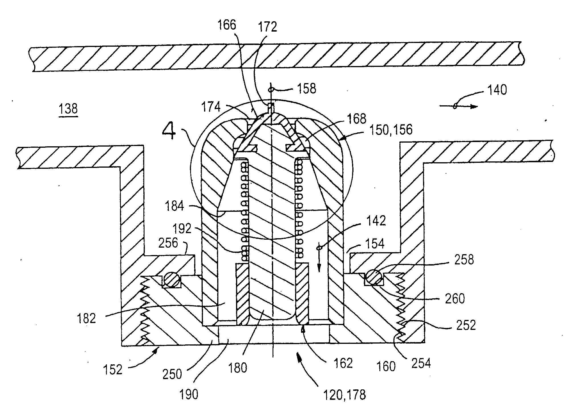
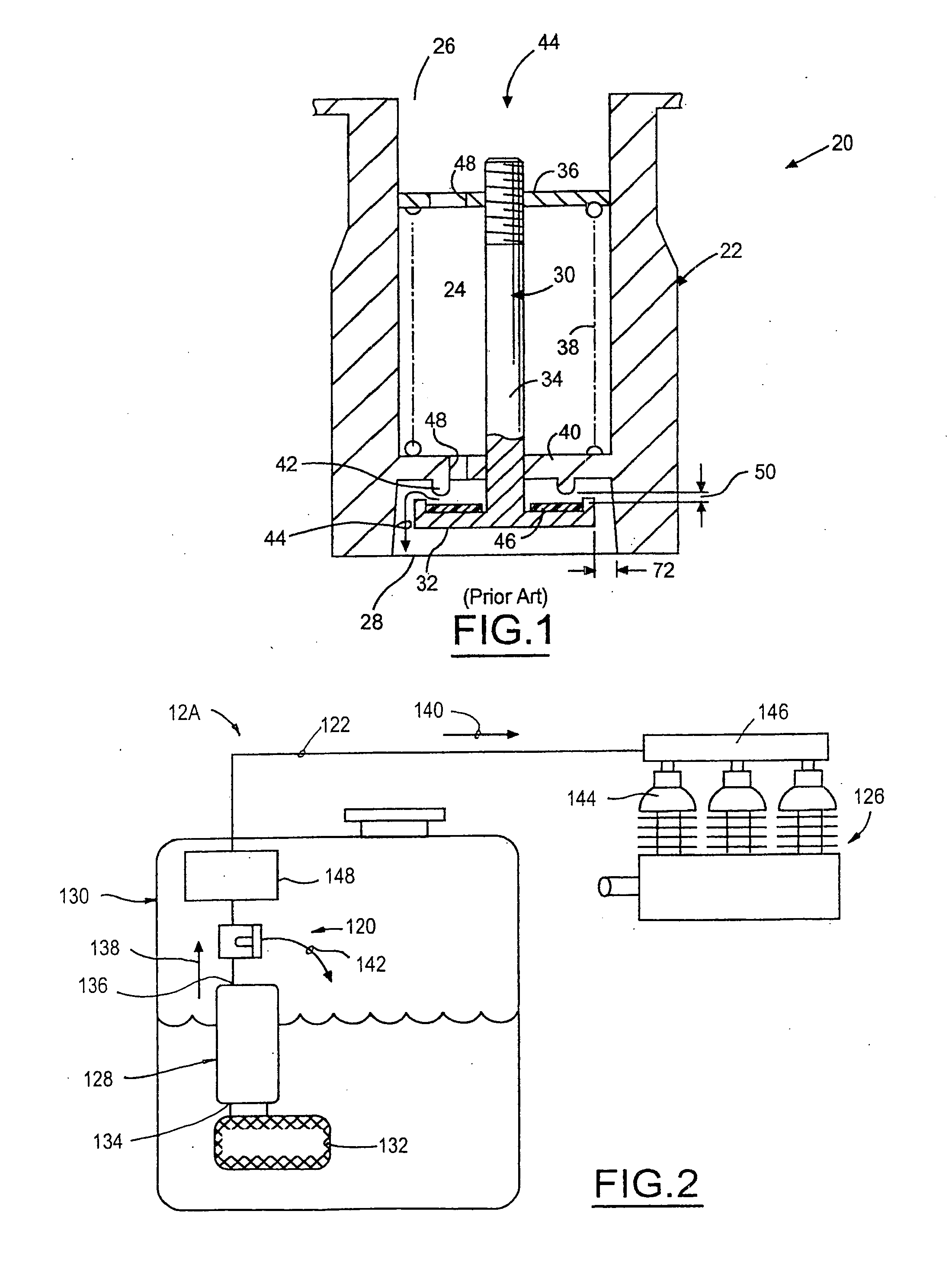
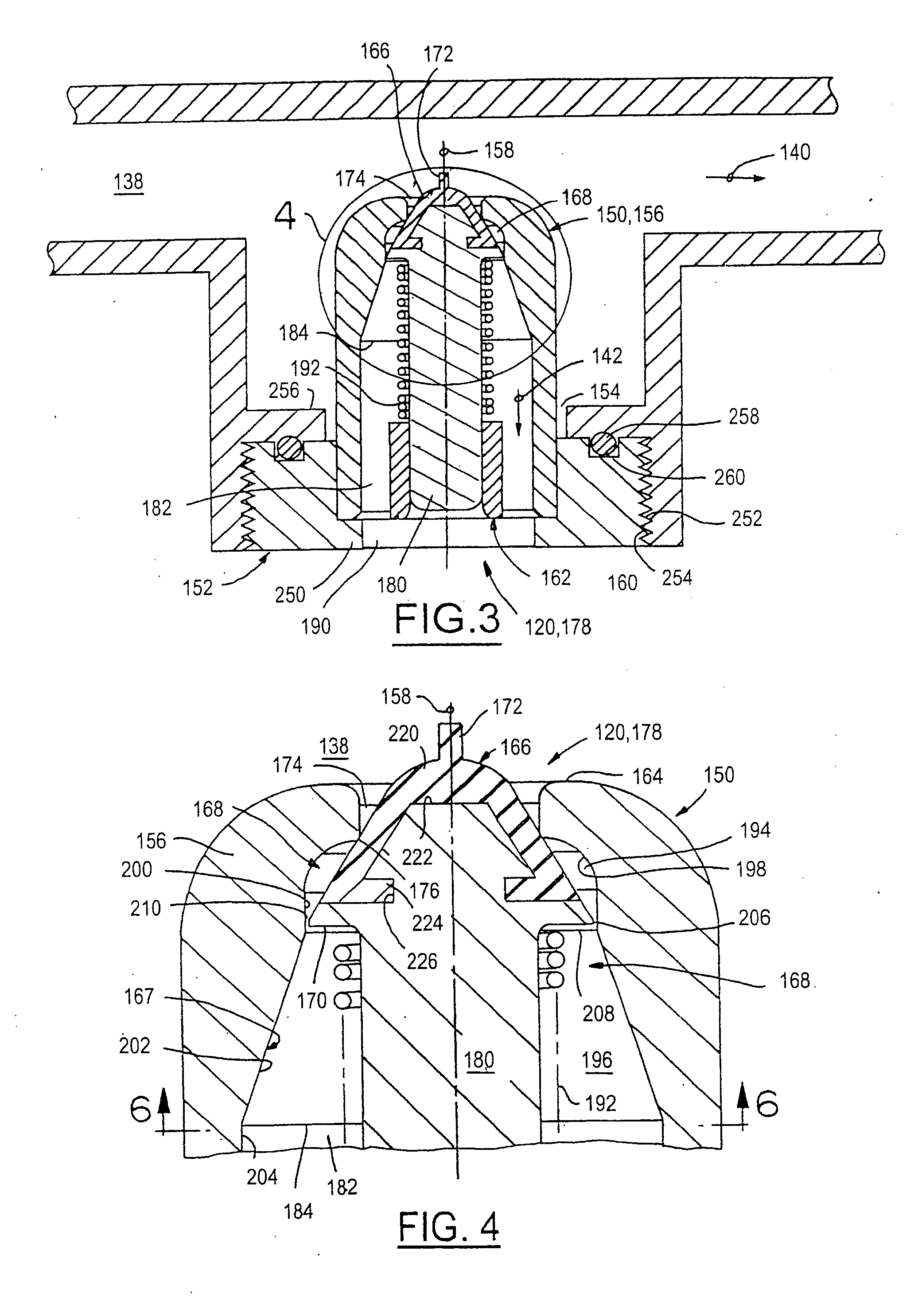
[0024]FIG. 3 illustrates a bypass pressure regulator 120 of the present invention utilized preferably in a flowing liquid conduit 122 which generally defines a supply passage or channel 138. FIG. 2 illustrates one preferred application of the regulator 120 in a preferably returnless fuel supply system 124 for a fuel injected combustion engine 126. In this particular application, the system 124 includes an electric fuel pump 128 preferably in a module located in a fuel tank 130. A pre-filter 132 is located generally at an inlet 134 of the fuel pump 128. The pump 128 supplies pressurized fuel at its outlet 136 which communicates directly with the channel 138 defined by the conduit 122 and to the bypass pressure regulator 120. The total output fuel flow from the pump 128 (indicated by arrow 139) is generally divided by the pressure regulator 120 as supply fuel to the engine (indicated by arrow 140) and bypass fuel (indicated by arrow 142). The total fuel output 139 flows into the bypas...


PUM


Abstract

A low cost bypass pressure regulator for liquid flowing preferably in a returnless fuel system for a combustion engine communicates operatively with a conduit which flows fuel from a fuel pump of the fuel system to at least one fuel injector of the combustion engine. The pressure regulator preferably has a valve head disposed at least in-part in a valve chamber defined by a circumferentially continuous inner surface carried by a valve body and which transitions radially outward with respect to a center axis and in a downstream direction. The valve head preferably tapers radially inward with respect to the center axis in an upstream direction and from a peripheral outer edge of the head. When the valve head is in a preferably biased closed position, the valve head is seated sealably against a seat carried by the body and the peripheral outer edge which is spaced radially downstream of the seat is radially spaced from, but fitted closely to the continuous inner surface thus defining a close fit region there-between. When the valve head is in an open position against the biasing forces of the pressure regulator, the tapered valve head is spaced appreciably away from the seat and the peripheral outer edge is spaced appreciably radially inward from the continuous inner surface thus defining a free flow region there-between. The movement of the valve head from closed to open is in a downstream direction, hence the free flow region is generally located downstream of the continuous inner surface portion which defined in-part the close fit region when the valve head was closed. Because the flow cross section spaced axially downstream of the seat generally enlarges as the valve head opens, a high velocity of liquid flow is moved away from the seat thus reducing the otherwise low pressure at the seat. By reducing or eliminating low pressure at the seat, oscillation of the valve head is reduced or eliminated.

Description

FIELD OF THE INVENTION [0001] This invention relates to pressure regulators and more particularly to a bypass pressure regulator for controlling the pressure and flow rate of liquid. BACKGROUND OF THE INVENTION [0002] In many liquid supply systems, and particularly fuel injection systems for combustion engines, it is desirable to supply liquid fuel to the fuel injectors from a fuel pump which continuously delivers a quantity of liquid fuel sufficient to supply the maximum fuel demand of the engine. Consequently, when the engine is operating under conditions which require less fuel, there is an excess of fuel being delivered from the fuel pump. This is especially true when the engine is idling and has an extremely low fuel demand while the fuel pump is still delivering a large quantity. [0003] In such systems, a bypass pressure regulator is utilized to divert or bypass the excess fuel from the needed supply of fuel consumed by the engine. Preferably, the bypass liquid fuel is diverte...

Claims


Application Information

Patent Timeline
IPC IPC(8): F02M37/00
CPCF02M37/0029F02M69/54F02M37/0082
Inventor DOUYAMA, YOSHIAKIGRIFKA, KERRY E.ISRAELSON, KEVIN L.ROCHE, RONALD H.TALASKI, EDWARD J.
Owner WALBRO LLC
Why Eureka
Try Eureka