Disc check valve

a technology valve components, which is applied in the field of disc check valves, can solve the problems of reducing the likelihood that the valve member will become jammed, reducing the cost associated with valve use, and reducing the likelihood of valve jamming, so as to reduce the likelihood, reduce the cost associated, and reduce the cost. the effect of cos

Inactive Publication Date: 2006-10-26
HALKEY ROBERTS CORP
View PDF23 Cites 10 Cited by
  • Summary
  • Abstract
  • Description
  • Claims
  • Application Information

AI Technical Summary

Benefits of technology

The design enhances fluid flow rates, reduces the likelihood of valve member jamming, maintains high seal integrity under differential pressures, and allows for visually monitored operation, achieving superior performance and cost-effectiveness compared to prior art.

Problems solved by technology

The valve was designed specifically for liquid applications, however limited gas media applications are possible with the design.
First, the finger like projections restrict the movement of the valve member in the valve body and significantly reduce the likelihood that the valve member will become jammed in the open or closed position.
Finally, the simplistic construction and operation of the valve decreases the costs associated with use of the valve.

Method used


Image

  • Disc check valve
  • Disc check valve
  • Disc check valve

Examples


Embodiment Construction

A. Seal Disc Configuration and Function:

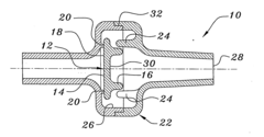
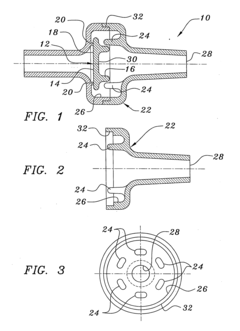
[0042] As shown in FIGS. 1-5, the new disc check valve utilizes a unique seal disc 12, employing a specific geometry to accomplish multiple specific functions in operation. The configuration of the seal disc 12 may be described as a flat circular disc 14 integrally mated to a modified, truncated torroidal shape 16 projecting from the downward-flow surface of the disc 12. The torroidal shape 16 is the key element of the design of the seal disc 12. This geometry provides the following functional features:

[0043] 1. The cylindrical mass of the torus 16 on one side of the disc 12 imparts structural rigidity to the seal, helping to keep the seal surface 18 of the disc 12 flat with respect to the annular seal 20 of the valve body 22. The torus 16 shape is positioned so as to have its mass over the annular seal 20. Deflection of the valve seal disc 12, and ultimate leakage or failure, is minimized under higher differential pressures. “Compression set...


PUM


Abstract

A free floating disc check valve is provided by the present application. The check valve includes a seal disc having an integral truncated torroidal shaped portion. The torroidal shaped portion provides structural rigidity to the seal disc to minimize deflection of the disc under higher differential fluid pressures. The torroidal shaped portion of the disc cooperates with finger-shaped projections inside the valve body to limit lateral displacement of the disc relative to the axial flow of the fluid. The torroidal shaped portion and the flat portion of the disc form a cup shape that creates a hydrodynamic force that assists in moving the disc to an opened or closed position. In one embodiment, the seal disc is made of an elastomeric material that is coated with a dry film lubricant. In another embodiment, the seal disc is made of a low density silicone.

Description

CROSS-REFERENCE TO RELATED APPLICATIONS [0001] This application is a continuation-in-part patent application of U.S. Pat. No. 6,988,510 issued Jan. 24, 2006 which claims the benefit of provisional application No. 60 / 366,590, filed Mar. 22, 2002, the disclosure of both of which are hereby incorporated by reference herein.BACKGROUND OF THE INVENTION [0002] 1. Field of the Invention [0003] This invention relates to check valves. More particularly, this invention relates to check valves for fluids employing a free-floating disc that allows fluid flow in an unchecked direction with a minimal increase in fluid pressure and turbulence while maximizing the rate of fluid flow through the valve. [0004] 2. Description of the Background Art [0005] Presently, there exist many types of disc valves that employ a free-floating disc that seats in a checked direction of fluid flow and unseats in an unchecked direction. Optimal designs of disc valves seek to minimize the increase in fluid pressure in ...

Claims


Application Information

Patent Timeline
Patent Type & AuthorityApplications(United States)
IPC IPC(8): F16K15/02
CPCF16K15/023Y10T137/792Y10T137/7904Y10T137/7036Y10T137/0491Y10T137/7856Y10T137/8359Y10T137/7854
InventorENERSON, JON R.
OwnerHALKEY ROBERTS CORP