

Recessed ceiling mounted passive infrared detector
- Summary
- Abstract
- Description
- Claims
- Application Information
AI Technical Summary
Benefits of technology
Problems solved by technology
Method used
Image

Examples
Embodiment Construction
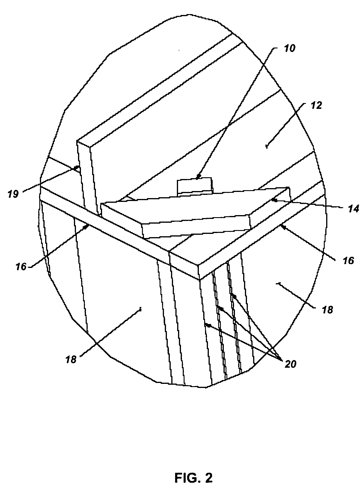
[0022] The preferred embodiments of the present invention will now be described with respect to the Figures. FIG. 2 illustrates the placement of a junction box 10 within the ceiling space of a premises. Typically, the corner of a room will have vertical supports 20 on which horizontal supports 16 will be located. An angle support 14 may also be used to reinforce the structural integrity of the construction. FIG. 2 also illustrates the placement of sheetrock for the ceiling 12 as well as the wall 18, all as well known in the art. FIG. 2 also illustrates the placement of the junction box 10 near or against the angle support 14, which will provide structural integrity and stability for subsequent mounting of the device as described herein. In the event that the device will be a wired-type device, then the wiring harness will be located such that the ends of the wires extend into the junction box 10 for later wiring (see FIG. 3). If, however, the device will be of the wireless type, the...
PUM
 Abstract
Description
Claims
Application Information