Conical bearingless motor/generator

Inactive Publication Date: 2006-10-26
UNIVERSITY OF TOLEDO
View PDF21 Cites 64 Cited by
  • Summary
  • Abstract
  • Description
  • Claims
  • Application Information

AI Technical Summary

Benefits of technology

[0011] The present invention is directed towards a bearingless motor/generator that meets the foregoing needs. The bearingless motor/generator comprises a rotatable part and a stationary part. The rotatable part is adapted to be rotated about an axis of rotation with respect to the stationary part. The stationary part has one or more windings for producing a drive field and a control field. The drive field is adapted to exert a tor

Problems solved by technology

However, this control system produces no forces for levitating the rotating part, since poles carry the same flux, and balance their forces out.
These additional elements increase the cost, size and we

Method used


Image

  • Conical bearingless motor/generator
  • Conical bearingless motor/generator
  • Conical bearingless motor/generator

Examples


Embodiment Construction

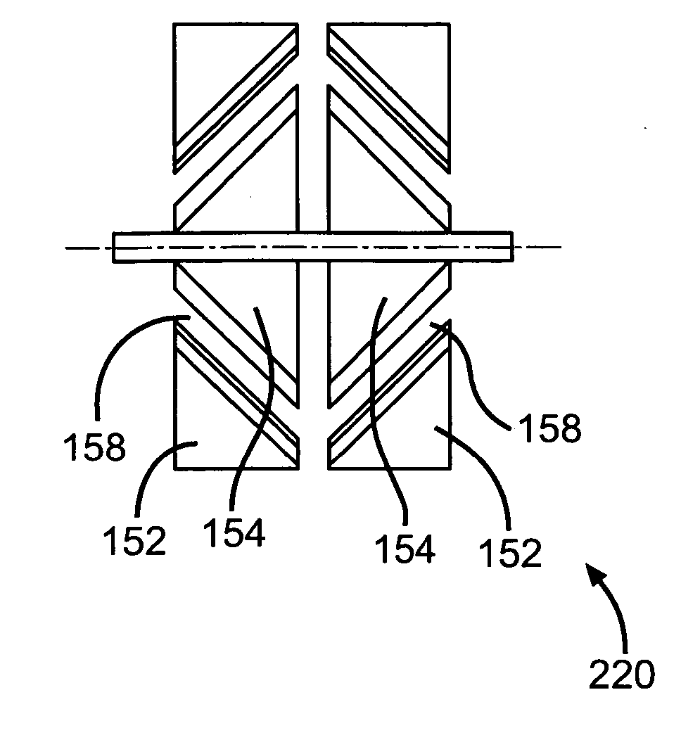
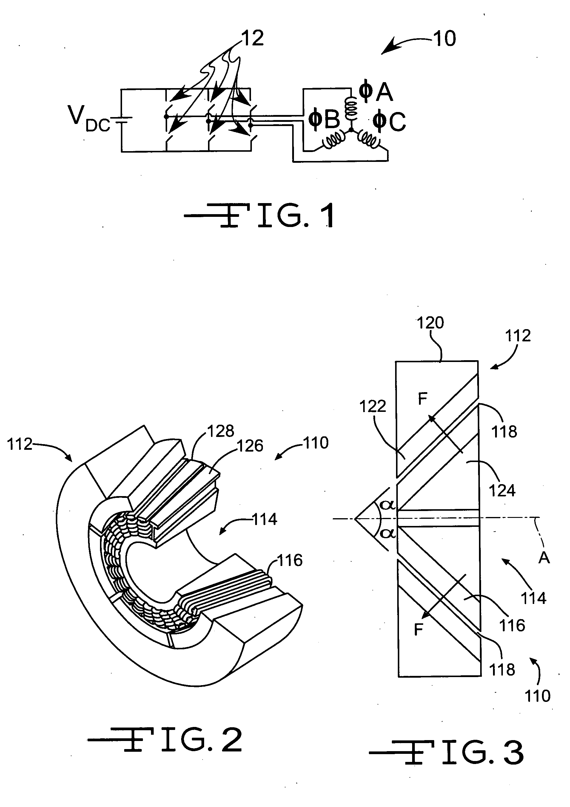
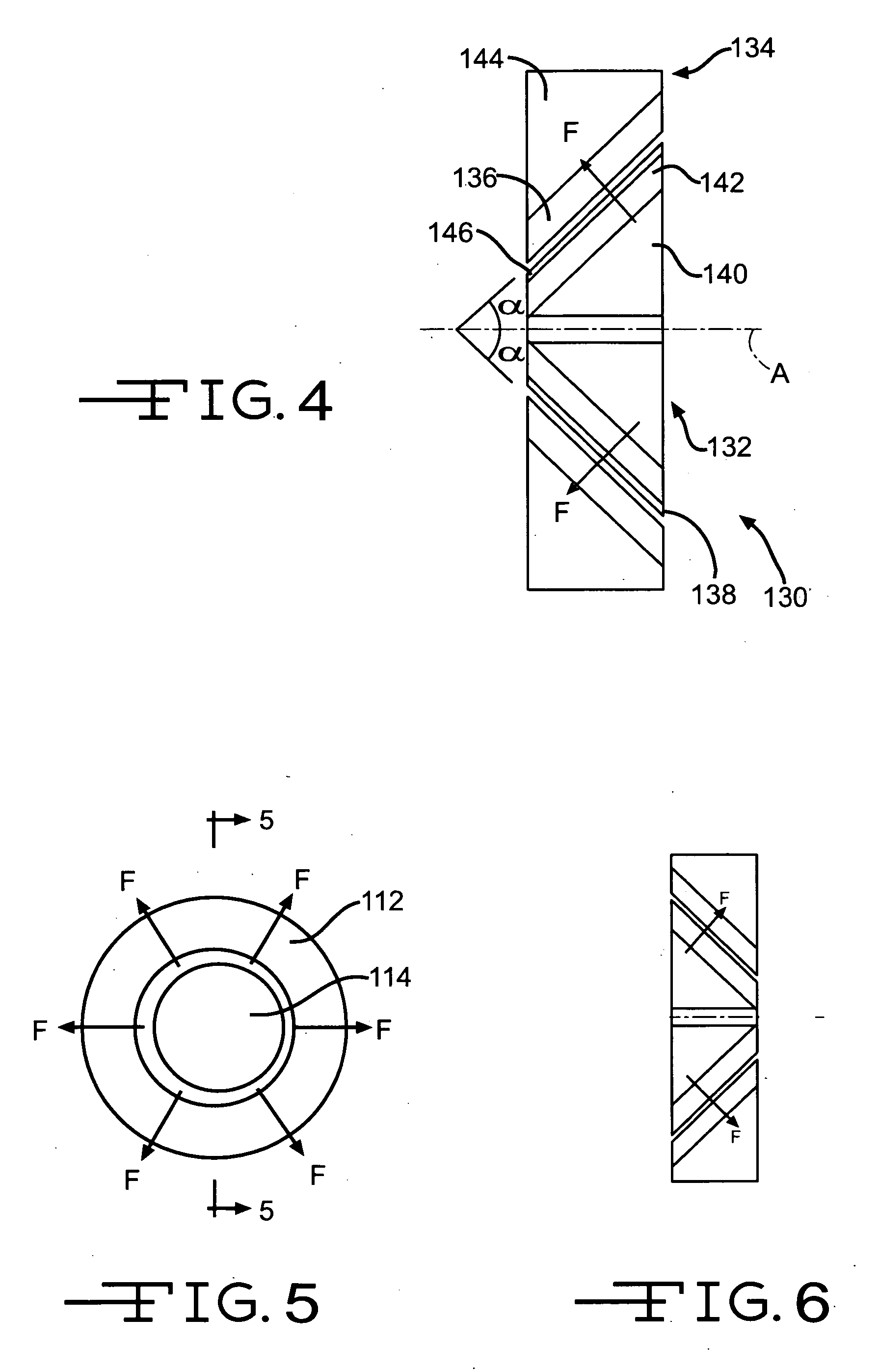
[0050] Referring now to the drawings, there is illustrated in FIGS. 3 and 4 a conical bearingless motor / generator, generally indicated at 110, according to a first embodiment of the invention. The term “motor / generator” should be clearly understood to mean that the conical bearingless motor / generator is adapted to function as either a motor or a generator. The conical bearingless motor / generator 110 comprises a rotatable part 112 and a stationary part 114. The rotatable part 112 is adapted to be rotated about an axis of rotation A (shown in FIG. 3) and with respect to the stationary part 114. The stationary part 114 has one or more windings 116 for producing both a drive field and a control field. The drive field is adapted to exert a torque on the rotatable part 112 that transfers energy between the rotatable part 112 and the stationary part 114.

[0051] As illustrated in FIG. 3, the control field is adapted to exert a force F on the rotatable part 112 to levitate the rotating part ...


PUM


Abstract

A bearingless motor/generator comprises a rotatable part and a stationary part. The rotatable part is adapted to be rotated about an axis of rotation with respect to the stationary part. The stationary part has one or more windings for producing a drive field and a control field. The drive field is adapted to exert a torque on the rotatable part to transfer energy between the rotatable part and the stationary part. The control field is adapted to exert a force on the rotatable part to levitate the rotatable part. The force is adapted to be directed at an angle greater than 0° and less than 90° relative to the axis of rotation of the rotatable part.

Description

CROSS REFERENCE TO RELATED APPLICATIONS [0001] This application a continuation-in-part of U.S. patent application Ser. No. 11 / 068,509, filed on Feb. 28, 2005, and U.S. patent application Ser. No. 11 / 304,359, filed on Dec. 15, 2005, the descriptions of which are incorporated herein by reference.[0002] This invention was made with government support under NCC3-916 and NCC3-924 awarded by NASA. The government has certain right in the invention.BACKGROUND OF INVENTION [0003] The present invention generally relates to an electromagnetic rotary drive and more particularly, to an electromagnetic rotary drive that functions as a bearingless motor / generator. The invention also relates to a control system for a bearingless motor-generator. [0004] Electromagnetic rotary drives are commonly used in standard motors as well as bearingless motor-generators. Conventional bearingless motor / generators are commonly used in flywheels, turbines, pumps and machine tools. Bearingless motor / generators typi...

Claims


Application Information

Patent Timeline
IPC IPC(8): H02K7/09
CPCF16C32/0491H02P21/05H02K7/09F16C32/0493F16C2380/26
Inventor KASCAK, PETER E.JANSEN, RALPH H.DEVER, TIMOTHY P.
Owner UNIVERSITY OF TOLEDO
Why Eureka
Try Eureka