Wiping unit for liquid droplet ejection head; liquid droplet ejection apparatus equipped therewith; electro-optical device; method of manufacturing the same; and electronic device

a technology of liquid droplet ejection and ejection apparatus, which is applied in the direction of coating, printing, electroluminescent light sources, etc., can solve the problems of increasing the consumption amount of expensive wiping sheets, clogging of ejection nozzles, and complex structure, so as to improve wiping performance and reduce the consumption amount of wiping sheets

Active Publication Date: 2006-10-26
KATEEVA
View PDF5 Cites 9 Cited by
  • Summary
  • Abstract
  • Description
  • Claims
  • Application Information

AI Technical Summary

Benefits of technology

[0013] This invention has an object of providing a wiping unit for a liquid droplet ejection head which can improve wiping performance and reduce a consumption amount of a wiping sheet to the extent possible, a liquid droplet ejection apparatus equipped with the same, an electro-optical device, a method of manufacturing the electro-optical device, and an electronic device.
[0015] According to the above-described arrangement, the surface of the wiping sheet is opposed to the cleaning liquid ejection member, and the cleaning liquid from the cleaning liquid ejection member is applied to the surface of the wiping sheet. Therefore, even if the cleaning liquid ejection member is arranged as close as possible to the pressing roller, a stain of the nozzle surface can be effectively wiped off by spreading the cleaning liquid on the surface of the wiping sheet. As a result, the length of the wiping sheet for a preliminary feeding (a feeding length until that part of the wiping sheet to which the cleaning liquid is applied by means of the cleaning liquid ejection member reaches the pressing roller) can be shortened to the extent possible, and the consumption amount of the wiping sheet can be reduced. Incidentally, since the cleaning liquid ejection member is arranged below the above-described horizontal surface, no interference thereof with the nozzle surface occurs.
[0017] Further, after the wiping of the nozzle surface, the wipe-off unit is moved in a direction opposite to the wiping direction to return to a home position. In this case, if the wiping sheet is kept pressed to the nozzle surface, there is a possibility of re-sticking of the wiped-off stain to the nozzle surface. Therefore, if the wipe-off unit is arranged to be freely movable vertically, and the wipe-off unit is moved back in its lowered state, the wiping sheet is separated from the nozzle surface. It is thus possible to prevent re-sticking of the stain to the nozzle surface during the back movement.
[0019] According to this arrangement, fiber fluff of the wiping sheet or a compound in a fiber is never dissolved. Moreover, by providing a certain thickness, the amount of a cleaning liquid necessary for the wiping operation can be adequately permeated and held therein.
[0021] According to this arrangement, since the nozzle surface of the liquid droplet ejection head can be managed to be in a state of no stains by the wiping unit, it is possible to maintain stable function liquid ejection and high imaging accuracy.
[0023] According to this arrangement, since the suction head and the wiping unit can be integrally moved by the moving mechanism, it is possible to efficiently cause the devices of such a maintenance system to face the liquid droplet ejection head moved to a maintenance position. For example, to solve an ejection failure of the liquid droplet ejection head, suction of function liquid and wiping of the liquid droplet ejection head can be continuously carried out without moving the liquid droplet ejection head.

Problems solved by technology

When an apparatus is paused for a relatively long period of time, such as stopping the apparatus, clogging may occur in the ejection nozzle due to increase in viscosity of a function liquid which remains in the liquid droplet ejection head.
In such a conventional wiping unit, wide planar distribution of a plurality of liquid droplet ejection heads in a carriage causes a problem of interference of the carriage with a main body portion of the wiping unit.
Moreover, since the wiping unit is moved by an X-axis table, and the liquid droplet ejection head (carriage) is moved up and down, there is a problem of a complex structure.
As a consequence, a consumption amount of the expensive wiping sheet increases to heighten running costs.
If the distance between the pressing member and the cleaning liquid ejection member is set large, the length of the wiping sheet wasted by the preliminary feeding becomes large.

Method used


Image

  • Wiping unit for liquid droplet ejection head; liquid droplet ejection apparatus equipped therewith; electro-optical device; method of manufacturing the same; and electronic device
  • Wiping unit for liquid droplet ejection head; liquid droplet ejection apparatus equipped therewith; electro-optical device; method of manufacturing the same; and electronic device
  • Wiping unit for liquid droplet ejection head; liquid droplet ejection apparatus equipped therewith; electro-optical device; method of manufacturing the same; and electronic device

Examples


Embodiment Construction

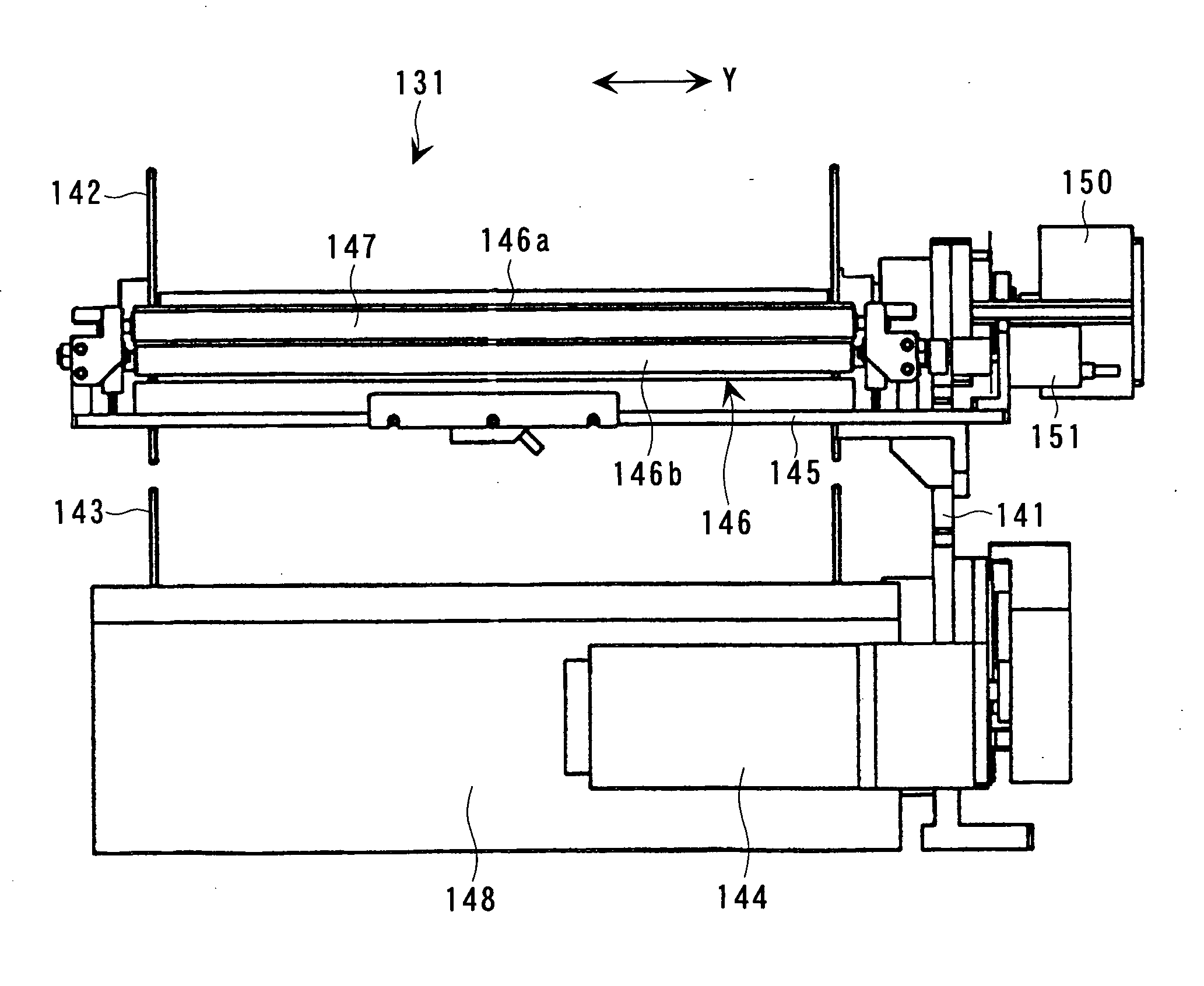
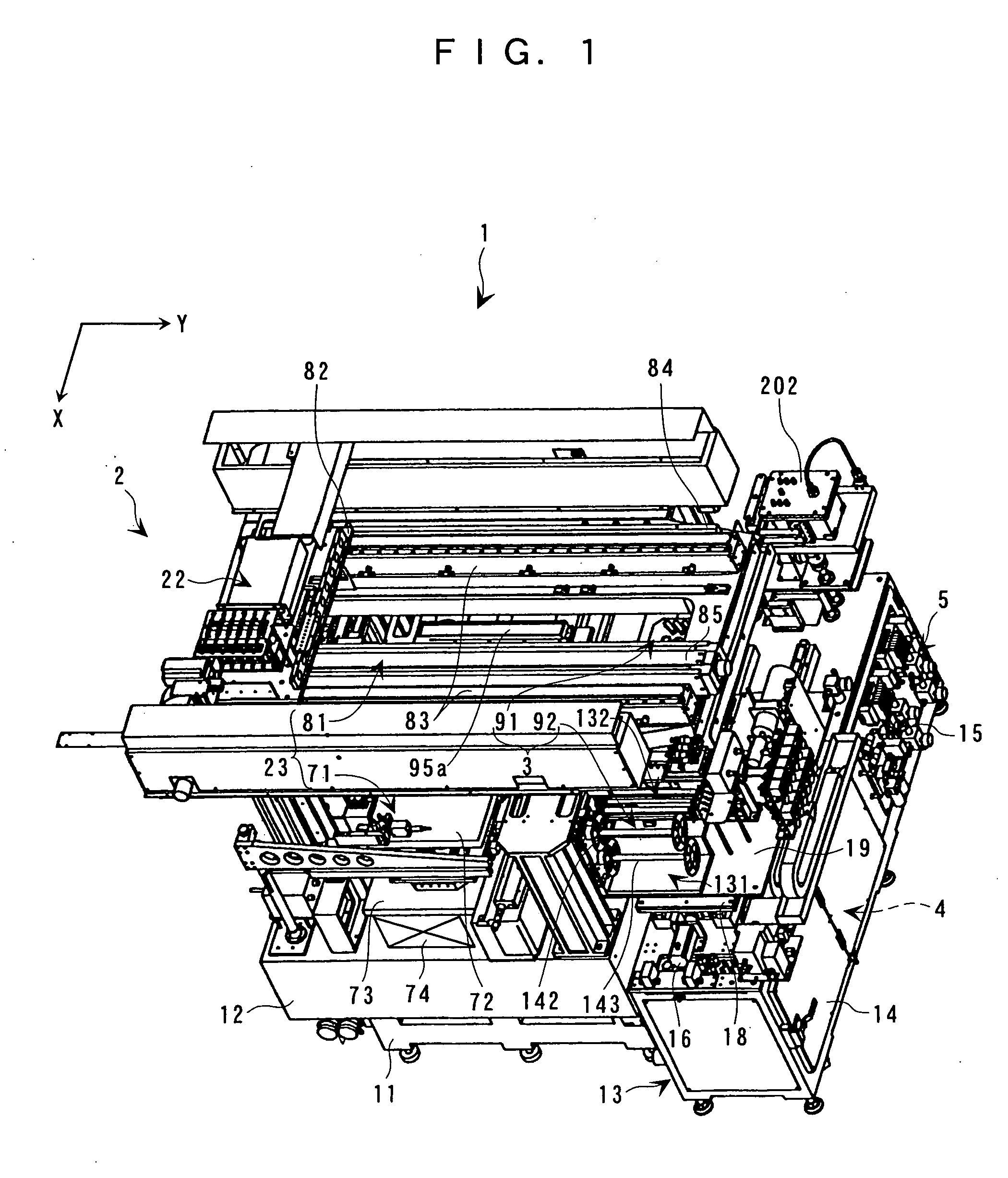
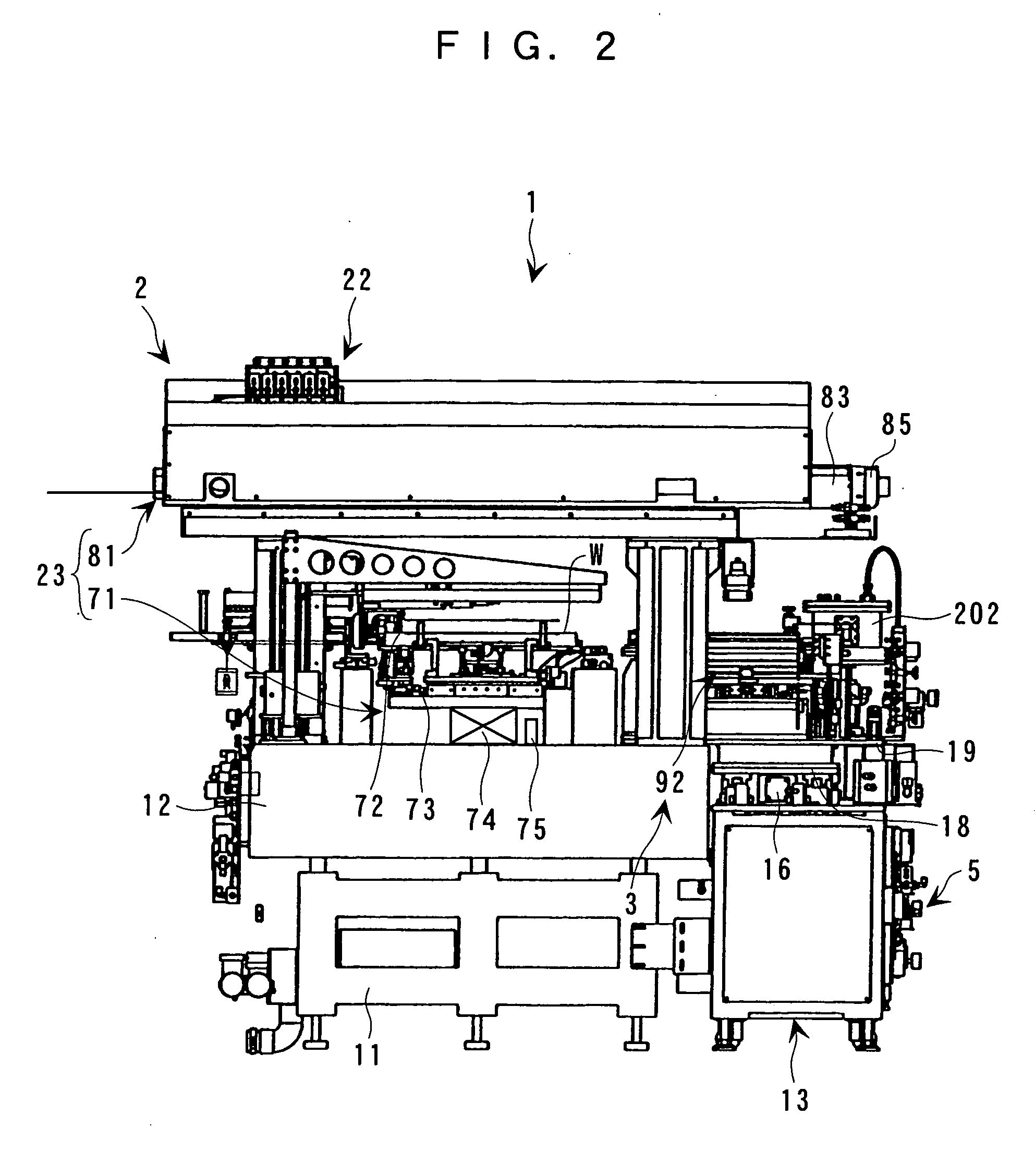
[0046] Herein below, the preferred embodiments of this invention will be described with reference to the accompanying drawings. FIG. 1 is an external perspective view of an imaging apparatus to which this invention is applied. FIG. 2 is a front view of the imaging apparatus to which this invention is applied. FIG. 3 is a right side view of the imaging apparatus to which this invention is applied. FIG. 4 is a plan view of the partially omitted imaging apparatus to which this invention is applied. As described in detail hereinafter, this imaging apparatus 1 introduces a special ink or a function liquid of a light-emitting resin or the like to a liquid droplet ejection head 31 to form a film-forming part on a workpiece W such as a substrate.

[0047] As shown in FIGS. 1 to 4, the imaging apparatus 1 is provided with imaging means 2 for ejecting the function liquid while moving the liquid droplet ejection head 31 relative to the workpiece W, maintenance means 3 for performing maintenance ...


PUM


Abstract

A wipe-off unit is provided with a cleaning liquid ejection member in a manner to be positioned below a horizontal surface coincident with a nozzle surface and on a sheet feeding side relative to a pressing roller. A wiping sheet is fed from below to the pressing roller through a space between the pressing roller and the cleaning liquid ejection member, and a cleaning liquid is applied to a surface of the wiping sheet.

Description

CROSS REFERENCE TO RELATED APPLICATIONS [0001] This application is a divisional patent application of U.S. Ser. No. 10 / 731,894 filed Dec. 9, 2003 which claims priority to JP 2002-369883 filed Dec. 20, 2002, all of which are hereby incorporated by reference.BACKGROUND OF THE INVENTION [0002] 1. Field of the Invention [0003] This invention relates to: a wiping unit for a liquid droplet ejection head in a liquid droplet ejection apparatus (imaging apparatus) which uses a liquid droplet ejection head as represented by an ink jet head; a liquid droplet ejection apparatus equipped with the same; an electro-optical device; a method of manufacturing the electro-optical device; and an electronic device. [0004] 2. Description of Related Art [0005] An ink jet head (liquid droplet ejection head) of an ink jet printer can accurately eject minute ink droplets (liquid droplets) in a dot shape. Thus, for example, by using a special ink or a function liquid of a photosensitive resin or the like as a...

Claims


Application Information

Patent Timeline
Patent Type & Authority Applications(United States)
IPC IPC(8): B41J2/165B05C5/00B05C11/10G02B5/20H01L51/50H05B33/10
CPCB41J2/16535B41J2/16579B41J2/16552B41J2002/1655B41J2/165
Inventor NAKAMURA, SHINICHI
Owner KATEEVA
Why Eureka
Try Eureka