
Capsule endoscope

a technology of endoscope and endoscope, which is applied in the field of endoscope, can solve the problems of inability to highly accurate diagnose the “barrett's esophagus", the esophagus tissue is very likely to turn cancerous, and the need for significant amount of power to drive, so as to achieve high frame rate and highly accurate diagnoses of conditions

Active Publication Date: 2006-10-26
OLYMPUS CORP
View PDF7 Cites 46 Cited by
  • Summary
  • Abstract
  • Description
  • Claims
  • Application Information

AI Technical Summary

Benefits of technology

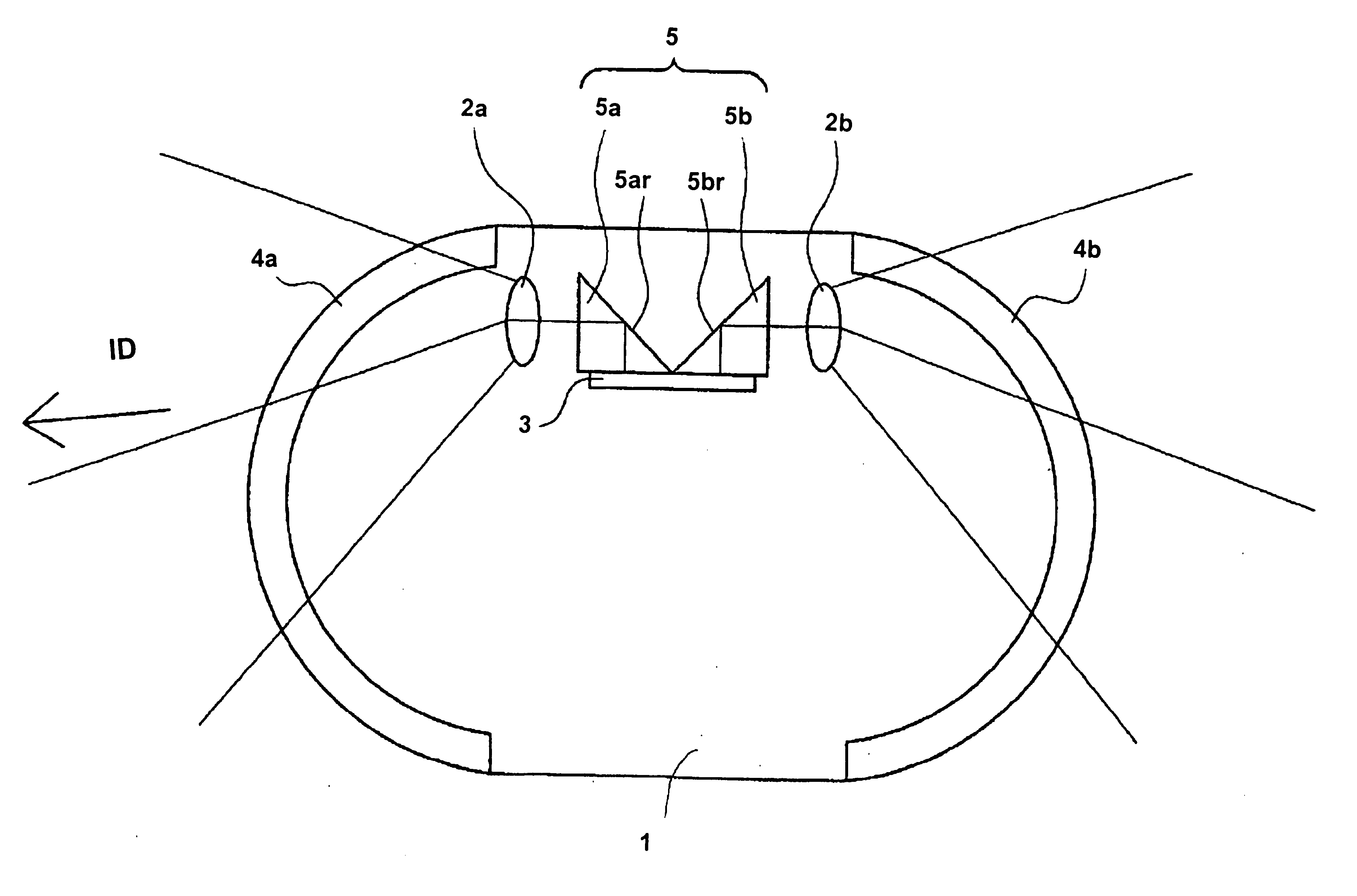
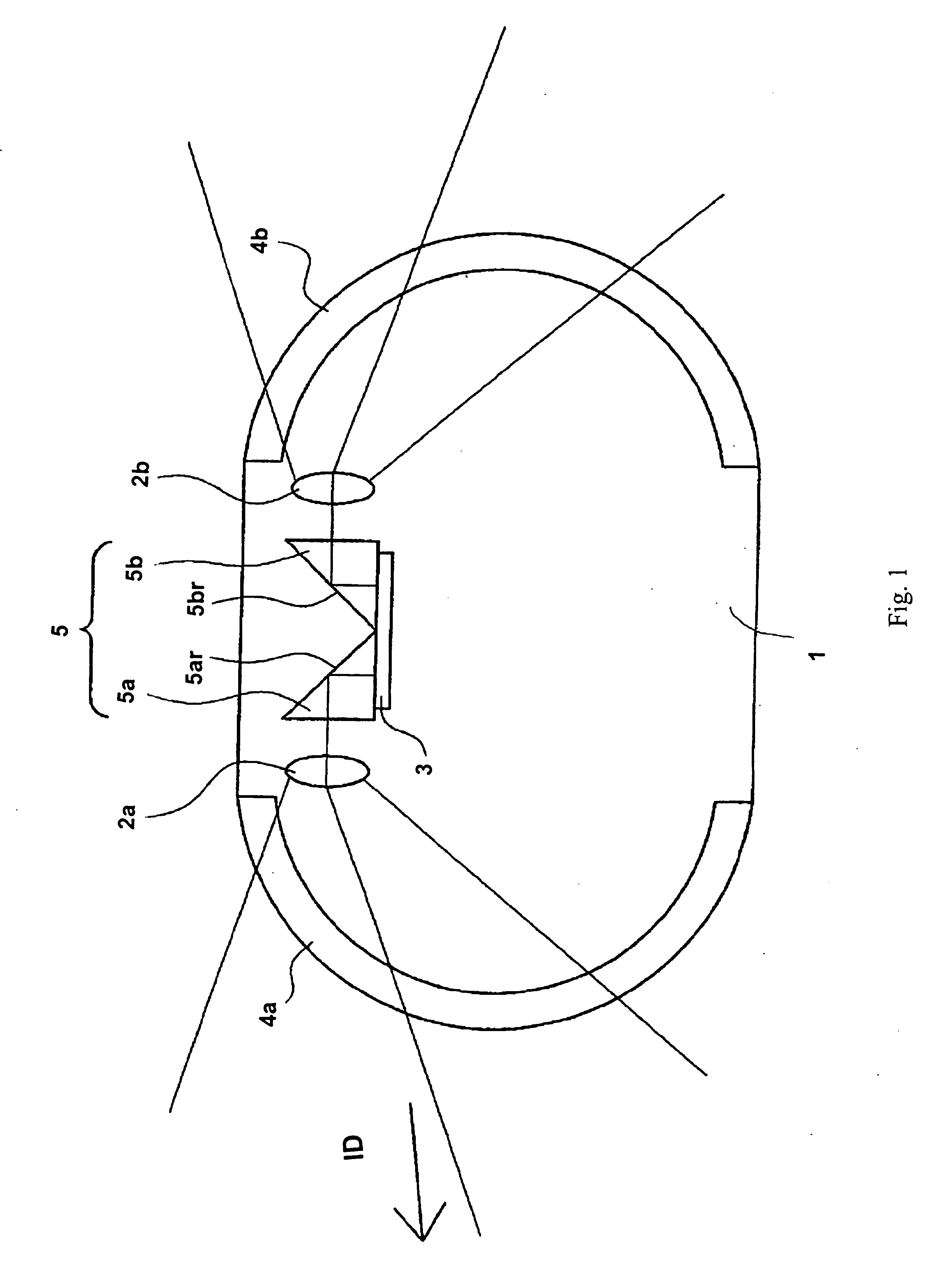
The present invention is about a small capsule endoscope that can capture images in two directions: one when the capsule is inserted and one opposite to the insertion direction. This allows for highly accurate diagnoses of conditions such as "Barrett's esophagus". The technical effect of this invention is improved image quality and more reliable diagnostic information.

Problems solved by technology

When the tissue of the esophagus has deteriorated to the point of “Barrett's esophagus,” the tissue of the esophagus is very likely to turn cancerous.
Therefore, the capsule endoscope disclosed in U.S. Pat. No. 6,939,295 is not capable of a highly accurate diagnosis of “Barrett's esophagus.”
However, when two image pickup devices are provided as in the capsule endoscope described in International Patent Publication WO 02 / 054932A2, the following problems occur.
First, a significant amount of power is required to drive a solid state image pickup element that forms an image pickup device such as a CCD.
Additionally, each CCD requires a drive circuit, inevitably increasing the capsule size in order to provide for a space in which to house the required structures.
Thus, the prior art capsule endoscope having two image pickup devices may fail to prevent “Barrett's esophagus” from being overlooked.

Method used


Image

  • Capsule endoscope
  • Capsule endoscope
  • Capsule endoscope

Examples


embodiment 1

[0097]FIG. 9 is a cross-sectional view along the optical axis of the optical structure from the transparent cover to the image pickup device of the capsule endoscope of Embodiment 1. FIG. 10 is an enlarged view of the objective optical system and image pickup device shown in FIG. 9. For convenience of illustration, only one optical system is illustrated.

[0098] In the capsule endoscope of Embodiment 1, the objective optical system 2a, the reflecting prism 5a, and the image pickup device 3 are arranged completely off the central axis of the dome-shaped transparent cover 4a, which coincides with the central axis of the capsule endoscope. In FIGS. 9 and 10, S is an aperture diaphragm, CG is a cover glass for protecting the image pickup surface of the image pickup device, and IM is the image pickup surface of the image pickup device. The capsule insertion direction and the opposite direction are indicated by a double-headed horizontal arrow at the bottom of FIG. 9. Additionally, the out...

embodiment 2

[0107]FIG. 11 is a cross-sectional view along the optical axis of the optical structure from the transparent cover to the image pickup device of the capsule endoscope of Embodiment 2. FIG. 12 is an enlarged view of the objective optical system and image pickup device shown in FIG. 11. For convenience of illustration, only one objective optical system is illustrated. The optical axis O of the objective optical system is indicated by a single-dashed line in FIGS. 11 and 12 and the central axis of the transparent cover is denoted as C′ in FIG. 11.

[0108] In the capsule endoscope of Embodiment 2, the objective optical system 2a, the reflecting prism 5a, and the image pickup device are arranged completely off the central axis of the dome-shaped transparent cover 4a, which coincides with the central axis of the capsule endoscope. In FIGS. 11 and 12, S is an aperture diaphragm, CG is a cover glass for protecting the image pickup surface of the image pickup device, and IM is the image picku...

embodiment 3

[0113]FIG. 13 is a cross-sectional view along the optical axis of the optical structure from the transparent cover to the image pickup device of the capsule endoscope of Embodiment 3. FIG. 14 is an enlarged view of the objective optical system and image pickup device shown in FIG. 13. For convenience of illustration, only one objective optical system is illustrated. The optical axis O of the objective optical system is indicated by a single-dashed line in FIGS. 13 and 14 and the central axis of the transparent cover is denoted as C′ in FIG. 13.

[0114] In the capsule endoscope of Embodiment 3, the objective optical system 2a, the reflecting prism 5a, and the image pickup device are arranged completely off the central axis of the dome-shaped transparent cover 4a, which coincides with the central axis of the capsule endoscope. In FIGS. 13 and 14, S is an aperture diaphragm, CG is a cover glass for protecting the image pickup surface of the image pickup device, and IM is the image picku...


PUM


Abstract

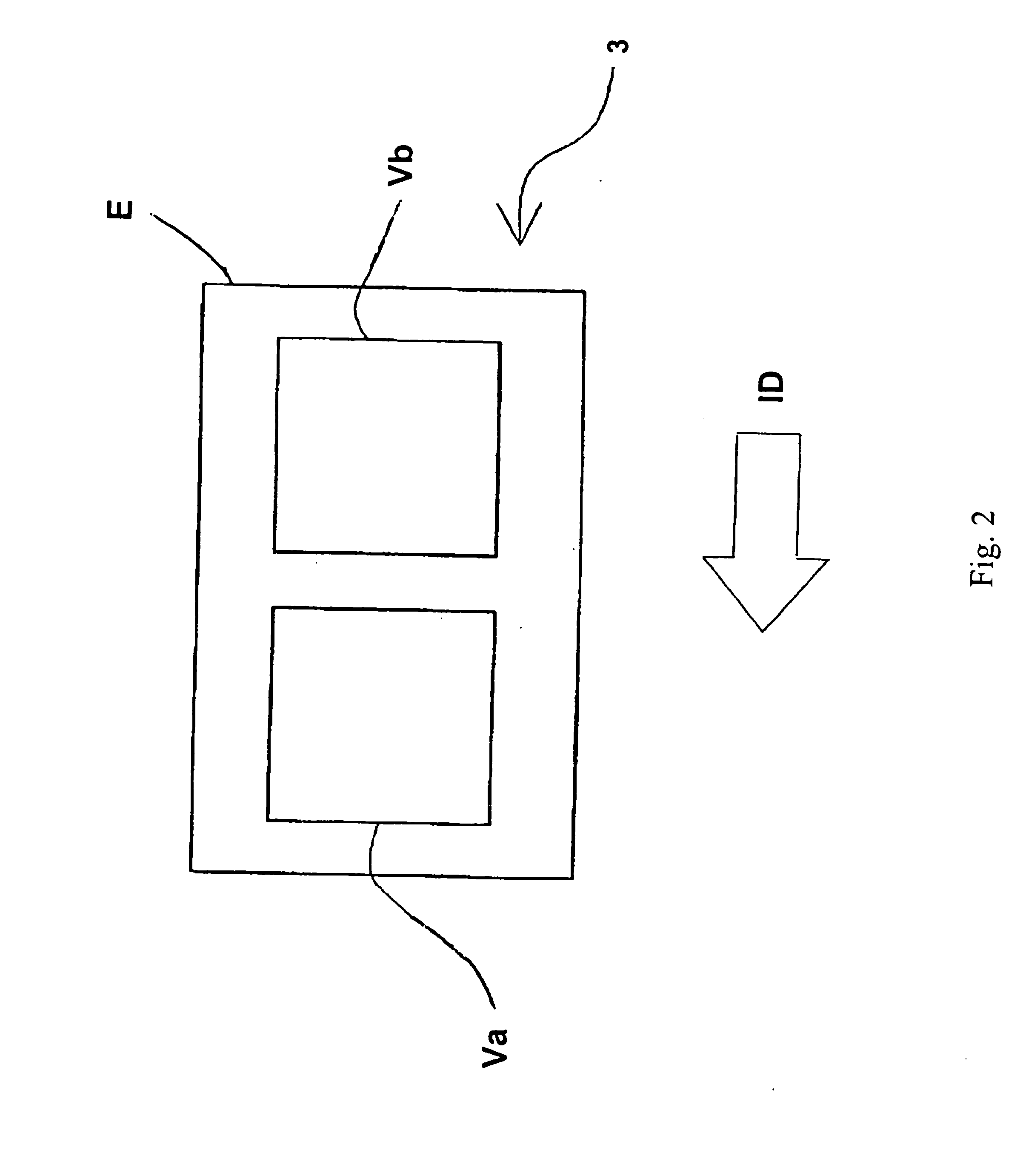
A capsule endoscope is disclosed that includes first and second objective optical systems for forming images of objects viewed in the capsule insertion direction and in the opposite direction on separate areas of one plane where an image pickup surface of an image pickup device is located. The capsule endoscope also includes illuminators for illuminating the objects, and a deflector or deflectors, such as reflecting prisms, for folding light from the objective optical systems to the image pickup surface so that the image pickup surface is parallel to the capsule insertion direction. The objective optical systems are retrofocus optical systems. The illuminators may have emission surfaces centered on the centers of spheres defined by dome-shaped transparent covers aligned along a central axis of the capsule endoscope. The objective optical systems, the deflector or deflectors, and the image pickup device are arranged completely off the central axis of the capsule endoscope.

Description

CROSS REFERENCE TO RELATED APPLICATION [0001] The present application claims benefit of priority under 35 U.S.C. § 119 of JP 2005-128,250, filed Apr. 26, 2005, the contents of which are hereby incorporated by reference.TECHNICAL FIELD OF THE INVENTION [0002] The present invention relates to a capsule endoscope for in vivo examination, particularly to a capsule endoscope that allows for observation of an image of an object in the capsule insertion direction and allows for observation of an image of an object in the direction opposite to the capsule insertion direction. BACKGROUND OF THE INVENTION [0003] Recently, capsule endoscopes have been increasingly used for making diagnoses of digestive organs in living bodies. Known prior art capsule endoscopes for these diagnoses are described in, for example, U.S. Pat. No. 6,939,295 and in International Patent Publication WO 02 / 054932A2. [0004]FIG. 21 shows an exemplary structure of a prior art capsule endoscope described in U.S. Pat. No. 6,...

Claims


Application Information

Patent Timeline
Patent Type & Authority Applications(United States)
IPC IPC(8): A61B1/04A62B1/04H04N7/18H04N9/47A61B1/06
CPCA61B1/00096A61B1/00179A61B1/0661A61B1/041A61B1/051A61B1/00188
Inventor KONNO, MITSUJIRO
Owner OLYMPUS CORP
Learn More