Exposure control system and method for an image sensor

a control system and image sensor technology, applied in the field of image sensing, can solve the problems of increasing the distance between the illumination source and the illumination source, increasing the cost of the illumination source, so as to achieve the effect of increasing the capture image quality

Inactive Publication Date: 2006-10-26
SUNPLUS INNOVATION TECH
View PDF5 Cites 24 Cited by
  • Summary
  • Abstract
  • Description
  • Claims
  • Application Information

AI Technical Summary

Benefits of technology

[0009] The object of the invention is to provide an exposure control system and method of an image sensor, which can avoid the prior problem that each row of pixels has a uniform exposure amount, and thus increase the captured image quality.
[0010] In accordance with one aspect of the present invention, there is provided an exposure control system for an image sensor. The system includes an image sensor, an illuminator, a controller and a light separator. The image sensor has plural photosensitive pixels in a two-dimensional matrix arrangement. When an exposure is operated in a sub-region of the plural photosensitive pixels, each row of pixels in the sub-region has an exposure state. The illuminator produces a flashlight as a light source for exposure. The controller is connected to the image sensor and the illuminator to control exposure timing of the image sensor and timing of producing the light source by the illuminator. The light separator is connected to the image sensor to reduce light interference and to allow the flashlight to be sent to the image sensor. The controller sequentially activates each row of pixels in the sub-region, and when all rows in the sub-region are in the exposure state, the controller drives the illuminator to produce the flashlight and controls a flashing period of the flashlight.
[0011] In accordance with another aspect of the present invention, there is provided an exposure control system for an image sensor. The system includes an image sensor, an illuminator, a controller and a light separator. The image sensor has plural photosensitive pixels in a two-dimensional matrix arrangement. When an exposure is operated in a sub-region of the plural photosensitive pixels, each row of pixels in the sub-region has an exposure state. The illuminator produces a flashlight as a light source for exposure. The controller is connected to the image sensor and the illuminator to control the exposure timing of the image sensor and the timing of producing the light source by the illuminator. The light separator includes a cover and a base. The image sensor, the illuminator and the controller are fixedly arranged inside the light separator in order to reduce light interference and allow the flashlight to be sent to the image sensor. The controller sequentially activates each row of pixels in the sub-region, and when all rows in the sub-region are in the exposure state, the controller drives the illuminator to produce the flashlight and controls a flashing period of the flashlight.

Problems solved by technology

As a result of a long exposure time, the illuminator cannot use a high-power light source otherwise the illuminator would be burned.
However, even though the illuminator consumes the smaller current, the exposure time is long so that the entire power consumption is relatively high.
However, such reduction may require a closer distance between the illuminator and an object surface.
Thus, the irradiated angle cannot be increased effectively.
In addition, the electronic shutter at each row of the CMOS image sensor needs to prolong its open time to obtain enough illumination.
Unfortunately, such a way may easily result in an image blur effect because of the long exposure time.
However, when an object is moving between TI and T2, its image may present a cracked effect.

Method used


Image

  • Exposure control system and method for an image sensor
  • Exposure control system and method for an image sensor
  • Exposure control system and method for an image sensor

Examples


Embodiment Construction

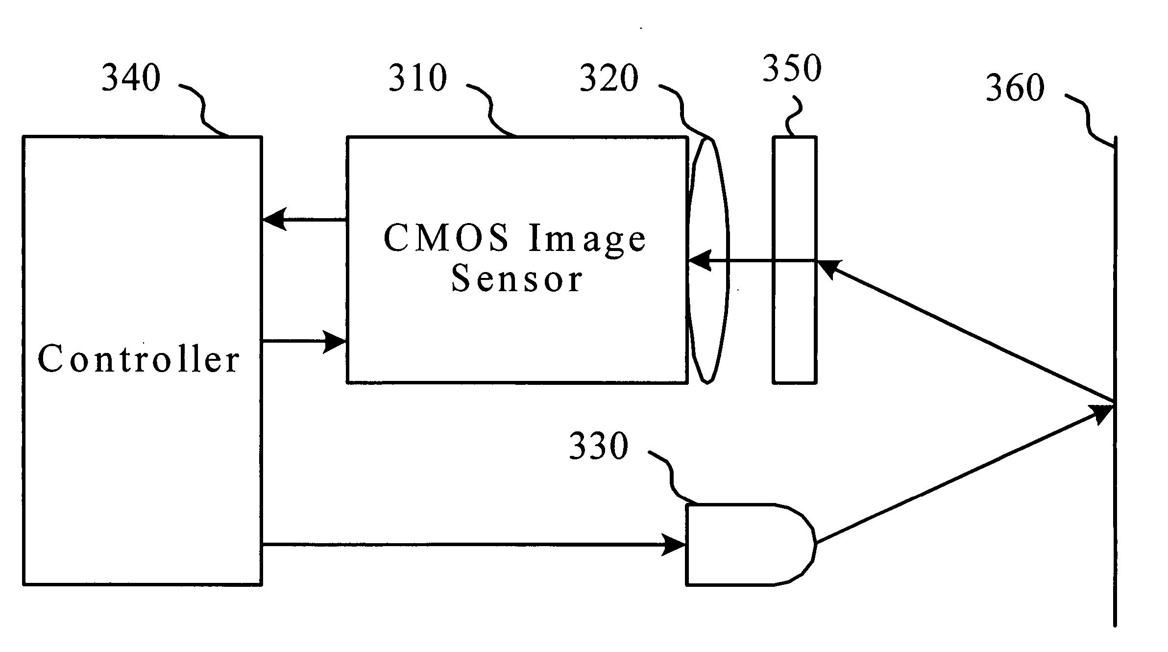
[0021]FIG. 3 is a block diagram of an embodiment of an exposure control system for an image sensor in accordance with the invention. As shown in FIG. 3, the system includes an image sensor 310, a convex set 320, an illuminator 330, a controller 340 and a light separator 350.

[0022] The image sensor 310 is a CMOS image sensor having plural photosensitive pixels in a 2D matrix arrangement. The CMOS image sensor 310 may have 640×480, 659×494, 752×480 photosensitive pixels, and the like. For different applications, the CMOS image sensor can set its active region to an appropriate size, i.e. a sub-region of the plural photosensitive pixels. For example, an active region of 320×240 is set for a 640×480 CMOS image sensor. In this embodiment, an exposure is operated in a sub-region of the plural photosensitive pixels, and the sub-region can have a size of 320×240, 96×96 or the entire region.

[0023] The illuminator 330 produces a flashlight as a light source for exposure to the image sensor ...


PUM


Abstract

An exposure control system and method for an image sensor, which includes an image sensor, an illuminator, a controller and a light separator. The image sensor has plural photosensitive pixels in a two-dimensional matrix arrangement. When an exposure is operated in a sub-region of the plural photosensitive pixels, the illuminator produces a flashlight as a light source for exposure. The light separator eliminates light except the flashlight. The controller sequentially activates each row of pixels in the sub-region, and when each row of pixels is in an exposure state, the controller drives the illuminator to produce the flashlight.

Description

BACKGROUND OF THE INVENTION [0001] 1. Field of the Invention [0002] The invention relates to the technical field of image sensing and, more particularly, to an exposure control system and method for an image sensor. [0003] 2. Description of Related Art [0004] In using an image sensor, a shutter is typically arranged in front of the image sensor to control the exposure amount and time for the image sensor. Such a shutter can be a mechanical or electronic shutter. In order to meet with compact size requirement, light and low cost requirement for a product, the electronic shutter has become the preferred device equipped with the image sensor. [0005] The electronic shutter uses an internal electronic signal of the image sensor to control the entire exposure timing and procedure. In a typical CMOS image sensor, the operations of reset, exposure and read of its internal devices are in a row-by-row manner. As shown in FIG. 1, a row will be reset before to expose the row of pixels. To have ...

Claims


Application Information

Patent Timeline
Patent Type & Authority Applications(United States)
IPC IPC(8): H04N5/222H04N5/235H04N5/353
CPCH04N5/3532H04N5/2354H04N23/74H04N25/531H04N1/02815H04N3/1562H04N23/72
Inventor LIAO, TUNG-TSAIFAN, KUO-CHUNCHEN, LI-MINGHSU, CHIA-KANG
Owner SUNPLUS INNOVATION TECH
Why Eureka
Try Eureka