

Imaging apparatus and monitoring system
a technology of imaging apparatus and monitoring system, which is applied in the field of imaging apparatus, can solve the problems of whites that cannot be seen clearly, and achieve the effect of reducing the uneven luminance distribution of objects and improving the quality of captured images
- Summary
- Abstract
- Description
- Claims
- Application Information
AI Technical Summary
Benefits of technology
Problems solved by technology
Method used
Image

Examples
first embodiment
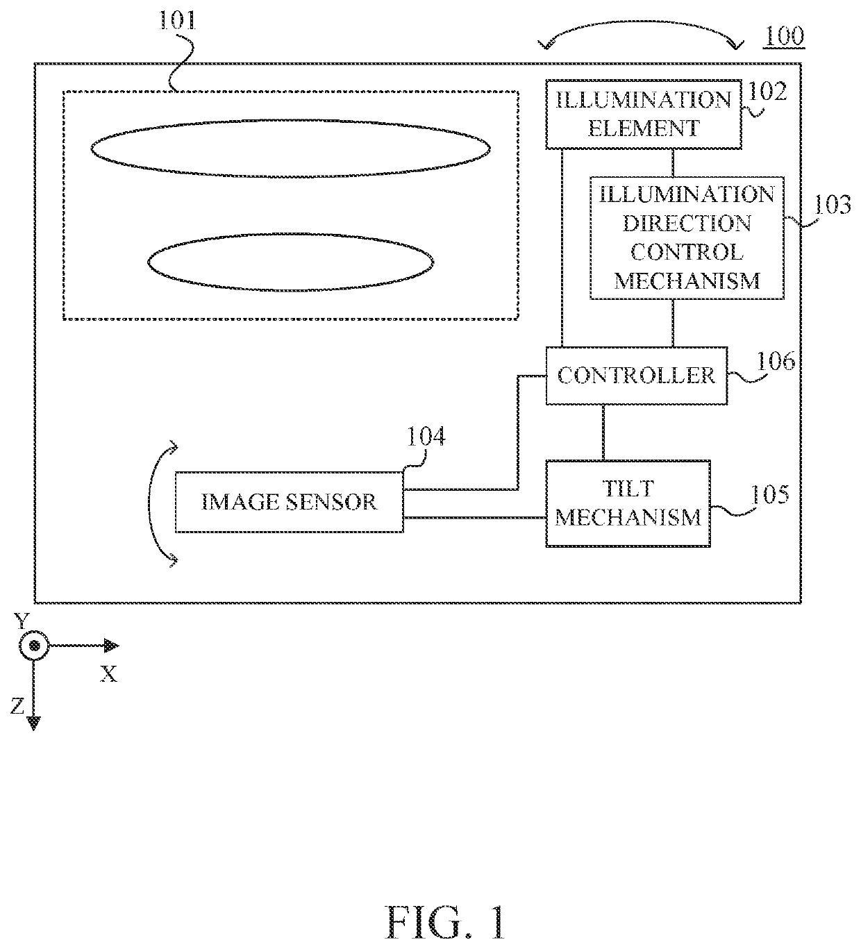
[0022]Referring now to FIG. 1, a description will be given of an imaging apparatus according to a first embodiment of the present invention. FIG. 1 is a block diagram of an imaging apparatus 100 according to this embodiment. The imaging apparatus 100 includes an imaging optical system (image capturing optical system) 101, an illumination element (illuminator) 102, an illumination direction control mechanism (illumination controller) 103, an image sensor (solid-state image pickup element) 104, and a tilt mechanism (angle controller) 105, and a controller 106. The controller 106 controls each component in the image apparatus 100. The imaging optical system 101 may be of a removable interchangeable lens type.
[0023]The image sensor 104 is a CMOS sensor or a CCD sensor, and photoelectrically converts an object image (optical image) formed through the imaging optical system 101. The illumination element 102 emits light having a wavelength to which the image sensor 104 is sensitive. For ex...
second embodiment
[0038]Referring now to FIG. 8, a description will be given of an imaging apparatus according to a second embodiment of the present invention. FIG. 8 is a block diagram of an imaging apparatus 200 according to this embodiment. The image sensor 200 according to this embodiment is different from the imaging apparatus 100 of the first embodiment described with reference to FIG. 1 in that it includes an illumination range control mechanism 213 that changes the illumination range (irradiation angle range) of the illumination element 102. The illumination range control mechanism 213 changes the illumination range of the illumination element 102 according to the first angle 111. This configuration can more effectively reduce the uneven illuminance on the focus plane 107 (object plane).
[0039]Referring now to FIGS. 9A and 9B, a description will be given of the illuminance distribution on the focus plane 107 (object plane) when the illumination range of the illumination element 102 is changed ...
third embodiment
[0044]Referring now to FIGS. 10A and 10B, a description will be given of an imaging apparatus according to a third embodiment of the present invention. FIG. 10A is a block diagram of an imaging apparatus 300 according to this embodiment, and FIG. 10B illustrates a relationship between the image sensor 104 and the illumination element 102 in tilt imaging.
[0045]Each of the imaging apparatuses 100 and 200 according to the above embodiments includes a single illumination element 102, and rotates the illumination element 102 itself to control the illumination direction, or drives a lens as part of the illumination optical system to control the illumination range. On the other hand, the imaging apparatus 300 according to this embodiment includes a plurality of illumination elements 321 and 322 (first and second illumination elements) both having different illumination directions and illumination ranges. This configuration enables the imaging apparatus 300 to control the effective illumina...
PUM
 Abstract
Description
Claims
Application Information