
Surgical Microscope

a microscope and surgical technology, applied in the field of surgical microscope systems, can solve the problems of difficult operation, difficult to see and operate units, and surgeons having to turn away from objects, so as to improve the operation of microscopes, improve the visibility and accessibility of input units, and increase the demand

Inactive Publication Date: 2006-10-26
LEICA MICROSYSTEMS (SCHWEIZ) AG
View PDF7 Cites 14 Cited by
  • Summary
  • Abstract
  • Description
  • Claims
  • Application Information

AI Technical Summary

Benefits of technology

[0009] It is the object of the present invention to improve the operation of a microscope, in particular of a surgical microscope. The intention in particular is to improve the visibility and accessibility of the input units, and the input is intended to meet increased demands in terms of asepsis, decreased cleaning requirement, and improved hospital hygiene in general.

Problems solved by technology

Such input units have the disadvantage that they are located in the nonsterile region, and must additionally be equipped with a display that, for example, also indicates the influence being exerted on a specific rotary controller
A necessary consequence of this type of installation is that because of their distance, such units are difficult for the surgeon to see and operate.
A disadvantage, however, is that the surgeon must turn away from the object or the surgical microscope if he or she wishes to view or operate this touch screen.

Method used


Image

  • Surgical Microscope
  • Surgical Microscope
  • Surgical Microscope

Examples


Embodiment Construction

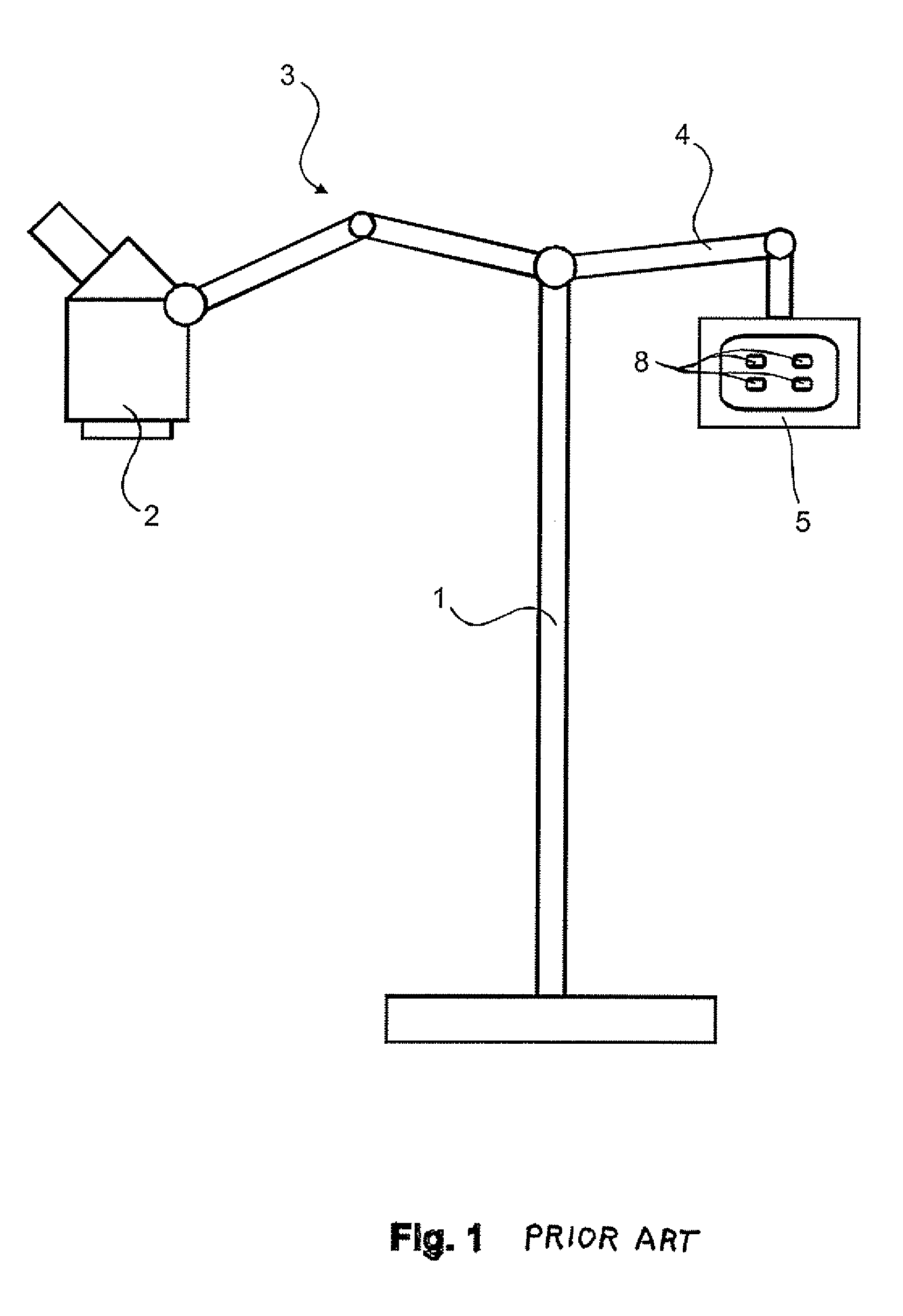
[0023]FIG. 1 depicts a conventional surgical microscope system according to the existing art. Two carrier arms 3 and 4 are supported on a stand 1. The one carrier arm 3 carries microscope body 2, and the other carrier arm 4 carries input unit 5. Input unit 5 comprises operating knobs and switches, of which four operating knobs 8 are shown for illustrative purposes.

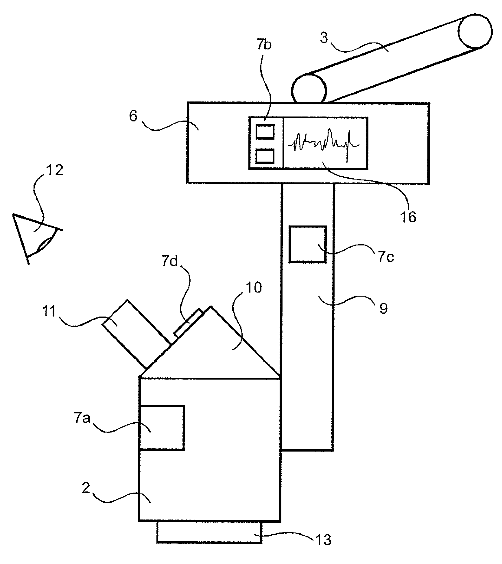
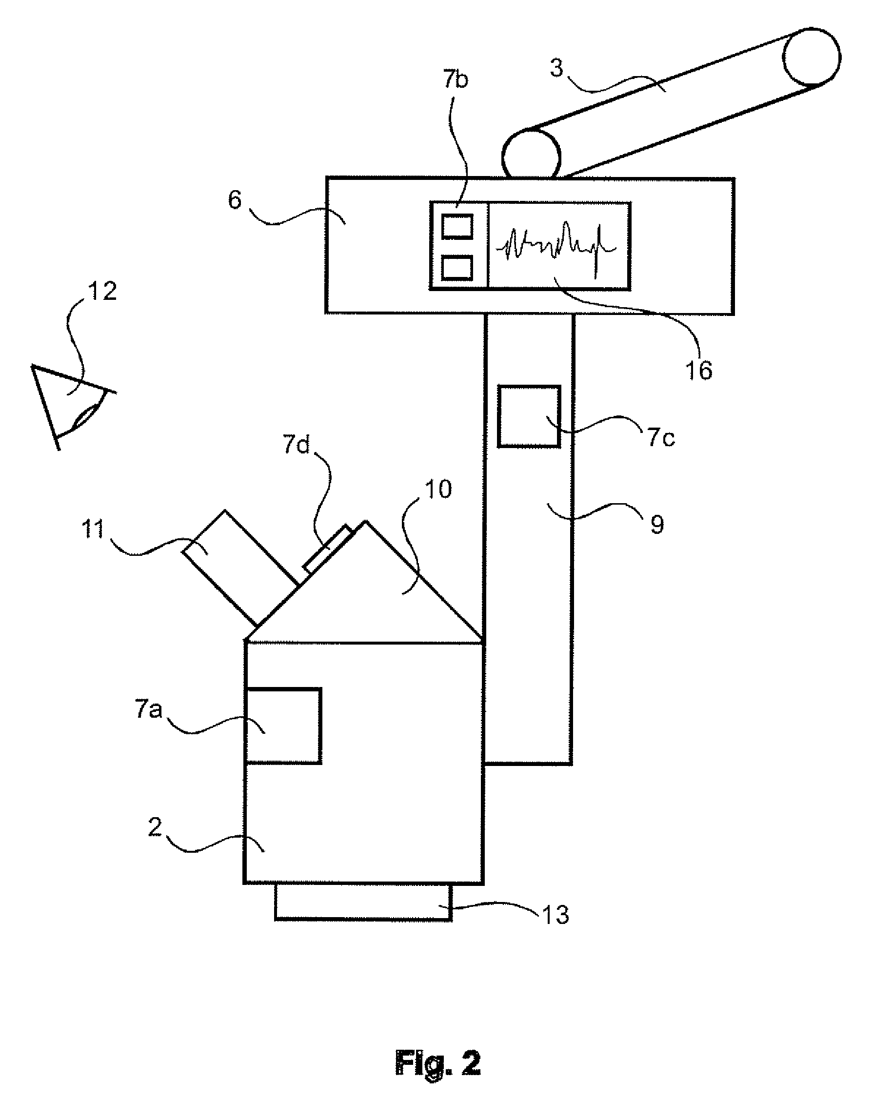
[0024]FIG. 2 shows only the a portion of a surgical microscope system, specifically X-Y coupling 6 and microscope body 2 which are secured pivotably on carrier arm 3. Microscope body 2 itself is carried by microscope carrier arm 9. The microscope comprises an objective 13 and an eyepiece tube 10 having eyepieces 11 (only one being visible) into which a symbolic viewer's eye 12 looks. Microscope body 2 with its constituents, in particular objective 13 and eyepiece tube 10, is referred to in the context of the present invention as an “optical unit.”

[0025] According to the present invention, at least one antimicrobial touch-...


PUM


Abstract

A surgical microscope system comprises a stand (1) with a carrier arm (3, 4), an optical unit having a microscope body (2), an objective (13), and at least one eyepiece tube (10), and at least one input unit (5) having a display and a touch-based operating panel, the touch-based operating panel (7) being antimicrobial, e.g. as a result of the addition of silver, copper, or other chemical substances having antimicrobial properties.

Description

CROSS REFERENCE TO RELATED APPLICATIONS [0001] This application claims priority of the German patent application 10 2005 018 431.6 filed Apr. 21, 2005 which is incorporated by reference herein. FIELD OF THE INVENTION [0002] The invention relates to surgical microscope systems, in particular to a surgical microscope system including an antimicrobial touch-based operating panel in an input unit thereof. BACKGROUND OF THE INVENTION [0003] A variety of input units are known in the existing art for operation of a microscope. [0004] For surgical microscopes, which require a very wide range of inputs for operation, complex input units in the form of operating consoles having switch knobs and multifunction switches, and optionally having display units, are necessary. Such input units have the disadvantage that they are located in the nonsterile region, and must additionally be equipped with a display that, for example, also indicates the influence being exerted on a specific rotary controll...

Claims


Application Information

Patent Timeline
Patent Type & Authority Applications(United States)
IPC IPC(8): G02B21/00
CPCA61B19/52A61B19/5223G02B21/0012A61B2017/00889G02B7/001A61B2017/00199A61B90/20A61B90/36
Inventor SANDER, ULRICH
Owner LEICA MICROSYSTEMS (SCHWEIZ) AG
Learn More