

High pressure pump having solenoid actuator
a technology of solenoid actuator and high-pressure pump, which is applied in the direction of pump, positive-displacement liquid engine, machine/engine, etc., can solve the problem that the structure of the solenoid valve may become complicated
- Summary
- Abstract
- Description
- Claims
- Application Information
AI Technical Summary
Benefits of technology
Problems solved by technology
Method used
Image

Examples
first embodiment
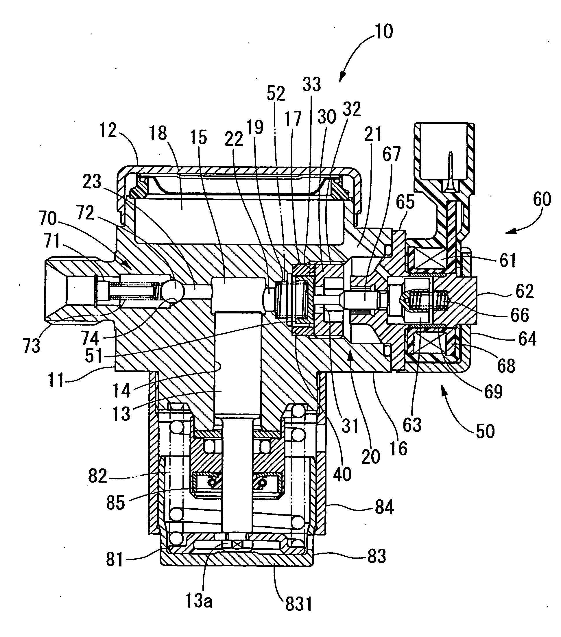
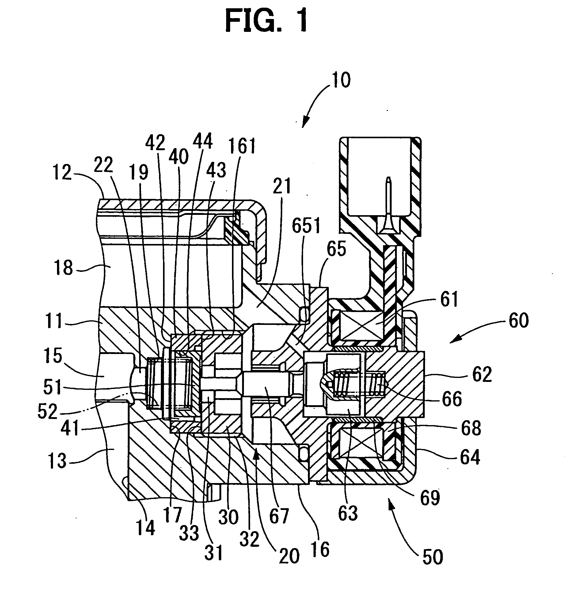
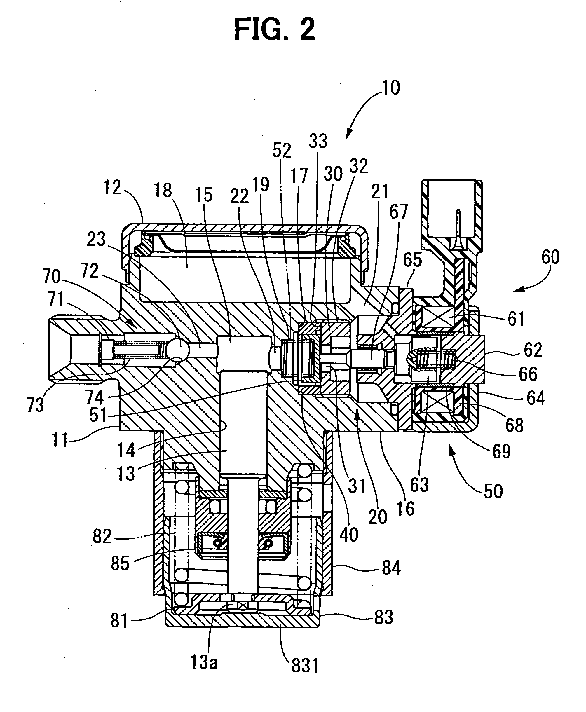
[0028] A high pressure fuel pump 10 of the first embodiment is described in reference to FIGS. 1, 2. This high pressure fuel pump 10 is a fuel pump for supplying fuel into an injector of a diesel engine and a gasoline engine, for example.
[0029] The high pressure fuel pump 10 has a housing main body 11, a cover 12, a plunger 13, a metering valve portion 50, a delivery valve portion 70, and the like. The housing main body 11 and the cover 12 construct a housing. The housing main body 11 is formed of martensitic stainless steel, or the like. The housing main body 11 has a cylinder 14, which is in a substantially cylindrical shape. The plunger 13 is movable with respect to a substantially axial direction of the plunger 13 in the cylinder 14 of the housing main body 11.
[0030] The housing main body 11 has an introducing passage 21, an inlet passage 22, a compression chamber 15, a delivery passage 23, and the like. The housing main body 11 has a cylindrical portion 16. The cylindrical po...
second embodiment
[0056] In the second embodiment shown in FIG. 3, the seat member 30 is press-fitted into the inner circumferential periphery of the cylindrical portion 16. Namely, the inner diameter of the cylindrical portion 16 is formed to be approximately equal to or slightly less than the outer diameter of the seat member 30. Thus, the seat member 30 is fixed to the inner circumferential periphery of the cylindrical portion 16, so that the guide member 40 is interposed between the seat member 30 and the housing main body 11.
[0057] In this second embodiment, the seat member 30 is welded to the housing main body 11 in a weld portion 91 formed in an end portion thereof on the opposite side of the guide member 40. When the seat member 30 is press-fitted into the cylindrical portion 16, the high pressure fuel pressurized in the compression chamber 15 mat be leaked into the solenoid actuator 60 through the portion between the inner circumferential face of the cylindrical portion 16 and the outer cir...
third and fourth embodiments
[0060] In the third embodiment, as shown in FIG. 4, the guide member is omitted from the structures of those in the first and second embodiments. In addition, a guide face 111 is formed in the housing main body 11. Namely, the housing main body 11 has the guide face 111 for guiding the movement of the plug 51. The inner circumferential face of the housing main body 11 defining the guide face 111 is slid on the outer circumferential face of the plug 51, thereby guiding the movement of the plug 51. The inner diameter of the guide face 111 of the housing main body 11 is less than the inner diameter of the cylindrical portion 16 accommodating the seat member 30. Therefore, the step face 17 is formed between the guide face 111 and the cylindrical portion 16.
[0061] A female screw portion 112 is formed in the inner circumferential periphery of the cylindrical portion 16. The female screw portion 112 is screwed to the male screw portion 32 of the seat member 30. The seat face 33 of the sea...
PUM
 Abstract
Description
Claims
Application Information