Connecting structure for magnesium diboride superconducting wire and a method of connecting the same
- Summary
- Abstract
- Description
- Claims
- Application Information
AI Technical Summary
Benefits of technology
Problems solved by technology
Method used
Image
Examples
example 1
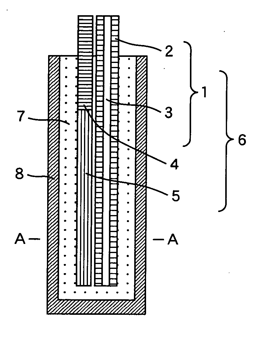
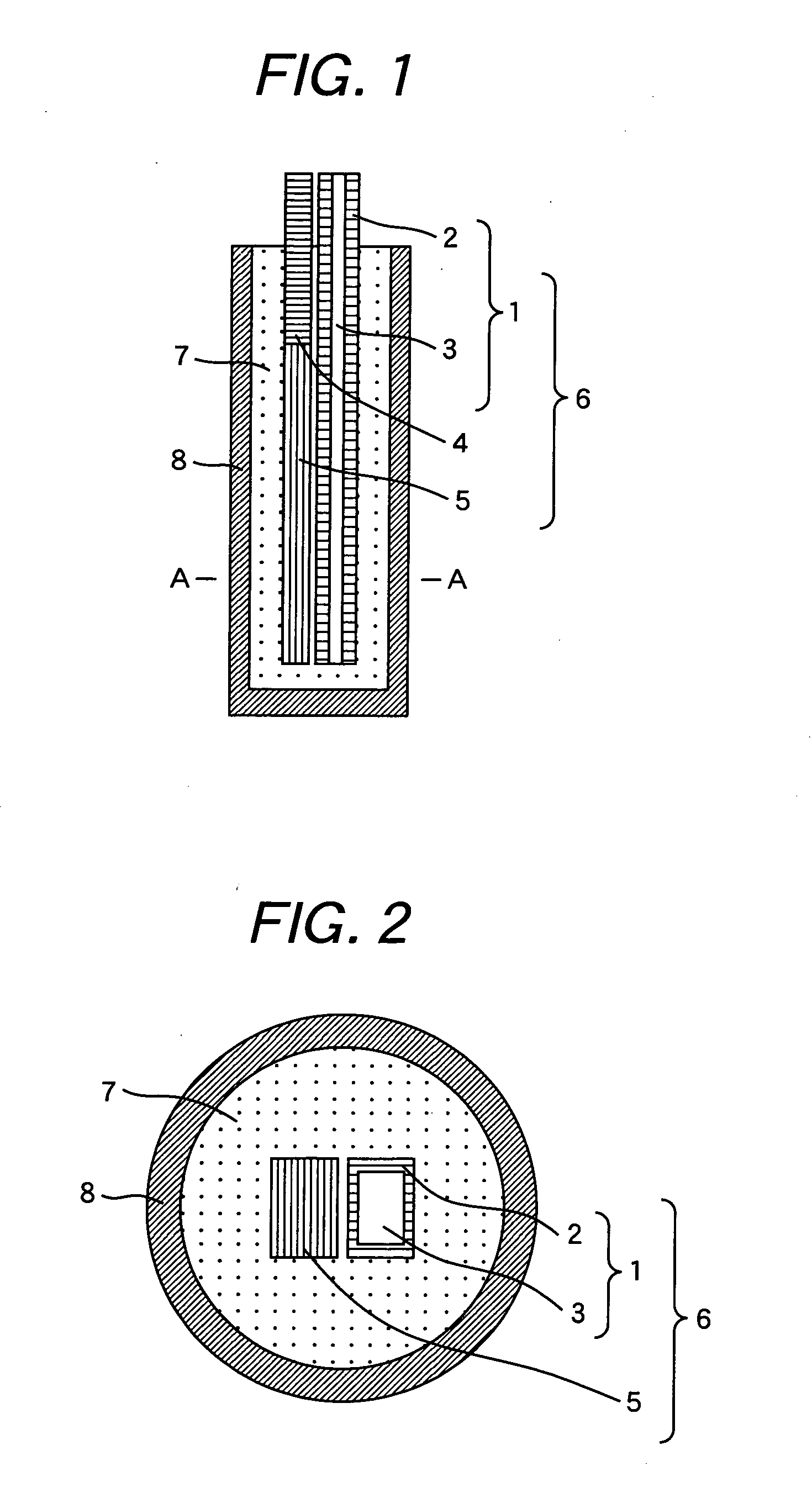
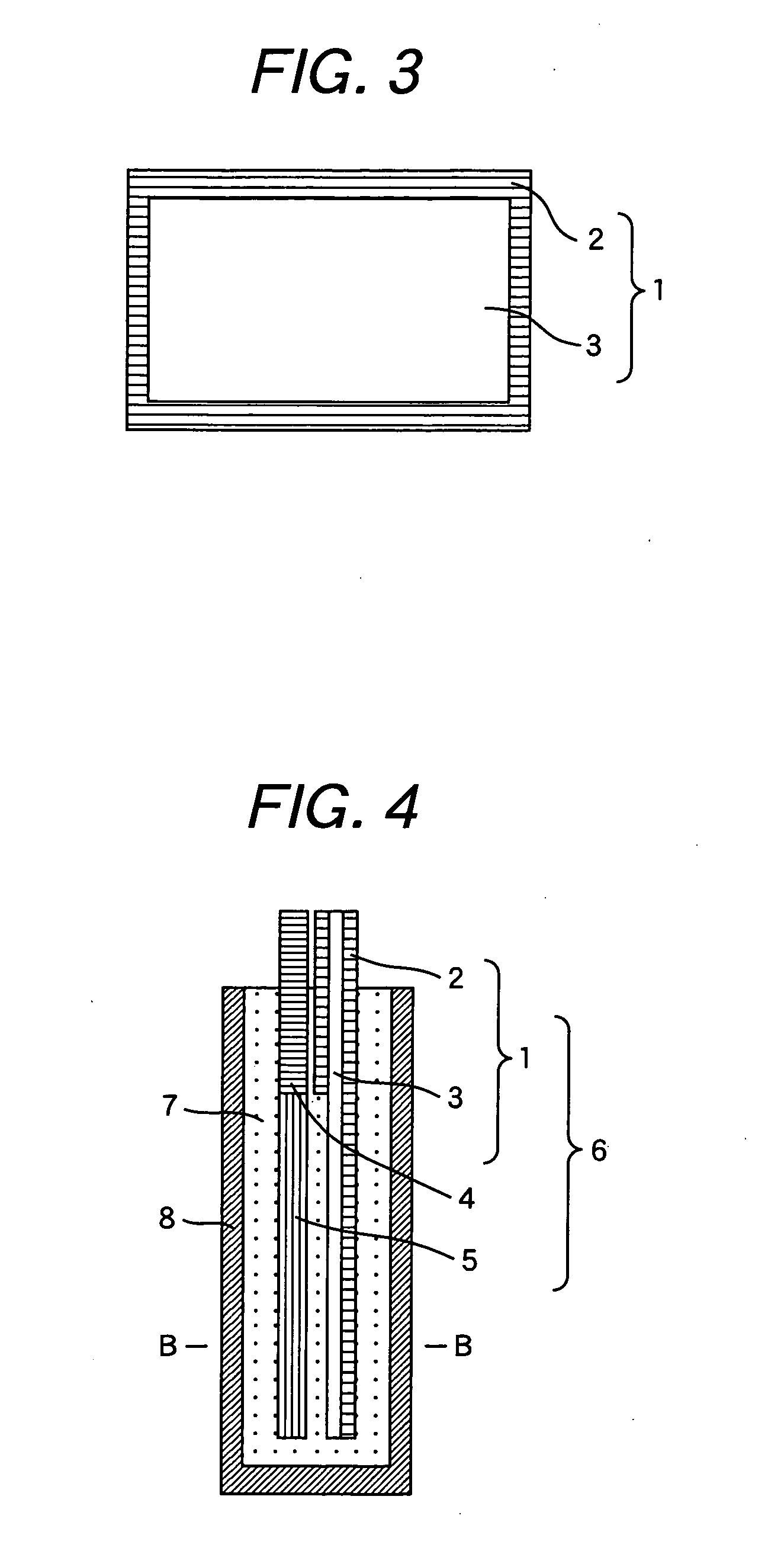
[0058]FIG. 6 is a cross sectional view showing a superconductive connection structure between a superconducting wire material according to the invention and other superconducting wire material, and FIG. 7 is a cross sectional view taken along line C-C in FIG. 6. FIG. 8 is a cross sectional view of an MgB2 wire used for the trial manufacture in this example. An MgB2 wire 9 has a metal sheath 2 of a highly conductive metal layer, an Nb tube 10 of a superconductive metal layer, and an MgB2 superconductive portion 3, a superconductive portion 5 of other superconducting wire 4 and an Nb tube 10 are fixed to form a wire material fixed portion 6, which are inserted into a connection metal tube 8 filled with a solder 7. In this connection method, the MgB2 superconductive portion 3 is connected by way of the Nb tube 10 to the solder 7 and other superconductive portion 5.
[0059] The structure of this example satisfies all the items I to III described above necessary for the superconductive co...
example 2
[0078] In this example, description is to be made for the structure of the MgB2 wire capable of various superconductive connections and the cross sectional connection structure thereof. In this example, in order not to expose the MgB2 superconductive portion, it is necessary for the superconductive connection of the MgB2 wire to cover the same with an alloy having a superconduction characteristic such as Nb or NbTi. In view of the above, after designing and manufacturing an MgB2 wire structure having such characteristics, it was superconductively connected with the NbTi wire in the same manner as described above.
[0079]FIG. 13 is a cross sectional view showing an example of a composite multi-core MgB2 wire. A composite multi-core MgB2 wire 14 has a structure in which an MgB2 superconductive portion 3 is surrounded with an Nb tube 10 and a plurality of them are buried in the metal sheath 2. Superconductive connection was conducted by using the MgB2 wire.
[0080]FIG. 14 is a cross sect...
example 3
[0081]FIG. 15 is a cross sectional view showing an example of a high strength MgB2 wire according to the invention. A high strength MgB2 wire 15 has a structure in which a high strength metal 16 and an MgB2 superconductive portion 3 are surrounded with an Nb tube 10 and they are arranged in a metal sheath 2. Superconductive connection was conducted by using the MgB2 wire.
[0082]FIG. 16 is a cross sectional view showing a superconductive connection structure using the composite multi-core MgB2 wire shown in FIG. 15. An Nb tube 10 filled with MgB2 superconductive portion 3, the MgB2 superconductive portion 3 of the high strength MgB2 wire 15, and a superconductive portion 5 of other superconducting wire 4 are fixed to form a wire material fixed portion 6, which is inserted into a connection metal tube 8 filled with the solder 7. Also in the connection mechanism, in the same manner as described previously, the metal sheath 2 is removed from the connection portion, and since the MgB2 su...
PUM
| Property | Measurement | Unit |
|---|---|---|
| Fraction | aaaaa | aaaaa |
| Electrical conductor | aaaaa | aaaaa |
| Strength | aaaaa | aaaaa |
Abstract
Description
Claims
Application Information
 - R&D
- Intellectual Property
- Life Sciences
- Materials
- Tech Scout
- Unparalleled Data Quality
- Higher Quality Content
- 60% Fewer Hallucinations
Browse by: Latest US Patents, China's latest patents, Technical Efficacy Thesaurus, Application Domain, Technology Topic, Popular Technical Reports.
© 2025 PatSnap. All rights reserved.Legal|Privacy policy|Modern Slavery Act Transparency Statement|Sitemap|About US| Contact US: help@patsnap.com


