Automatic gearshifting process for a vehicle with engaged coupling-dependent power take off and automatic disengagement process of a coupling-dependent power take off

Inactive Publication Date: 2006-10-26
VOLVO LASTVAGNAR AB
View PDF26 Cites 13 Cited by
  • Summary
  • Abstract
  • Description
  • Claims
  • Application Information

AI Technical Summary

Benefits of technology

[0026] This ensures that the gear can be disengaged so that the transmission can assume neutral position and the control unit can engage a new gear and that the claw clutch can be disengaged. This produces increased comfort in the vehicle. A further advantage is that wear in the claw clutch and in the gear concerned is reduced.
[0027] In a further preferred embodiment based on any one of the above-stated processes, the gear and the claw clutch are respectively equipped with means for deterring accidental disengagement, i.e., coupling teeth with cutbacks, for example. The fact that, according to the invention, the control unit limits the power tapping from the power take off serves to reduce the applied torque and hence minimize the force required to disconnect the engaging/disengaging device

Problems solved by technology

In order to minimize wear and possible damage, however, torquelessness is aimed for in the gear before it is disengaged.
A problem with the prior art is that, in the case of an engaged coupling-dependent power take off, in which power is being tapped and in which a gear engaged in the transmission and equipped with means for preventing unwanted disengagement in the transfer of torque at the gear is simultaneously to be disengaged, the disengagement of the gear is unachievable, because of the said means.
Equivalent disengagement problems exist in power take offs in which the engaging/disengaging device of the power take off is constituted by a claw clutch with corresponding means for deterring accidental disengagement, i.e., through some form of coupling teeth with cutbacks.
Another problem with gearshifting with engaged coupling-dependent p

Method used


Image

  • Automatic gearshifting process for a vehicle with engaged coupling-dependent power take off and automatic disengagement process of a coupling-dependent power take off
  • Automatic gearshifting process for a vehicle with engaged coupling-dependent power take off and automatic disengagement process of a coupling-dependent power take off
  • Automatic gearshifting process for a vehicle with engaged coupling-dependent power take off and automatic disengagement process of a coupling-dependent power take off

Examples


Embodiment Construction

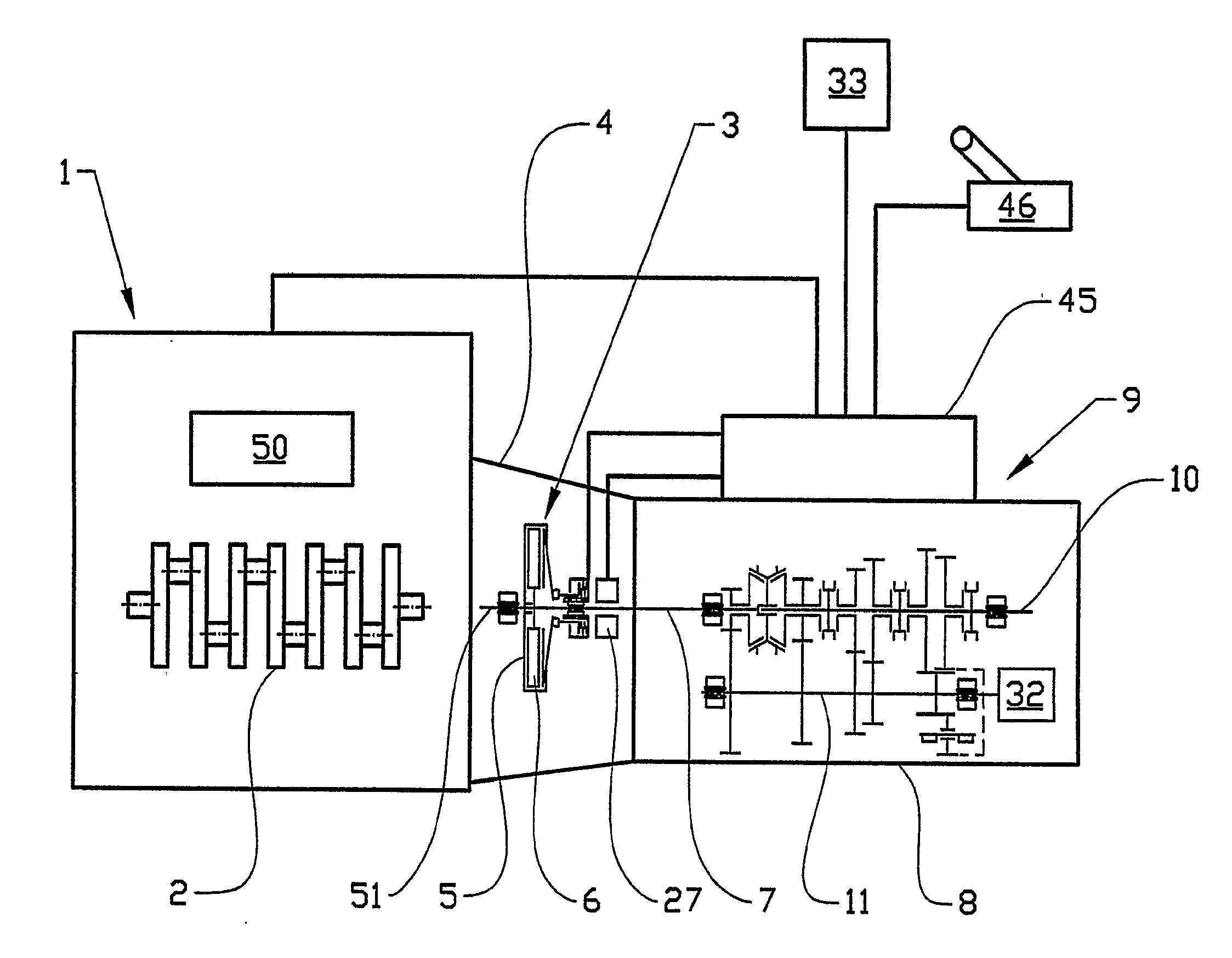
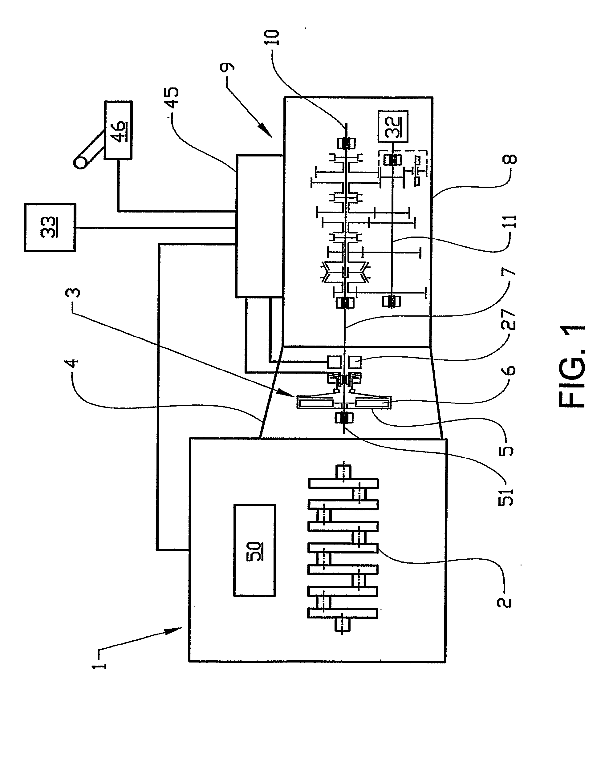
[0031] In FIG. 1, a six-cylinder internal combustion engine, for example a diesel engine, is denoted by 1, the crankshaft 2 of which is coupled to a single-disk dry plate clutch denoted generally by 3, which is enclosed in a clutch case 4. The crankshaft 2 is non-rotatably connected by the output shaft 51 of the engine, which is connected with the flywheel (not shown), to the clutch housing 5 of the plate clutch 3, whilst the plate disk 6 thereof is non-rotatably connected to an input shaft which is rotatably mounted in the housing 8 of a transmission denoted generally by 9.

[0032] Also rotatably mounted in the housing 8 are a main shaft 10 and an intermediate shaft 11.

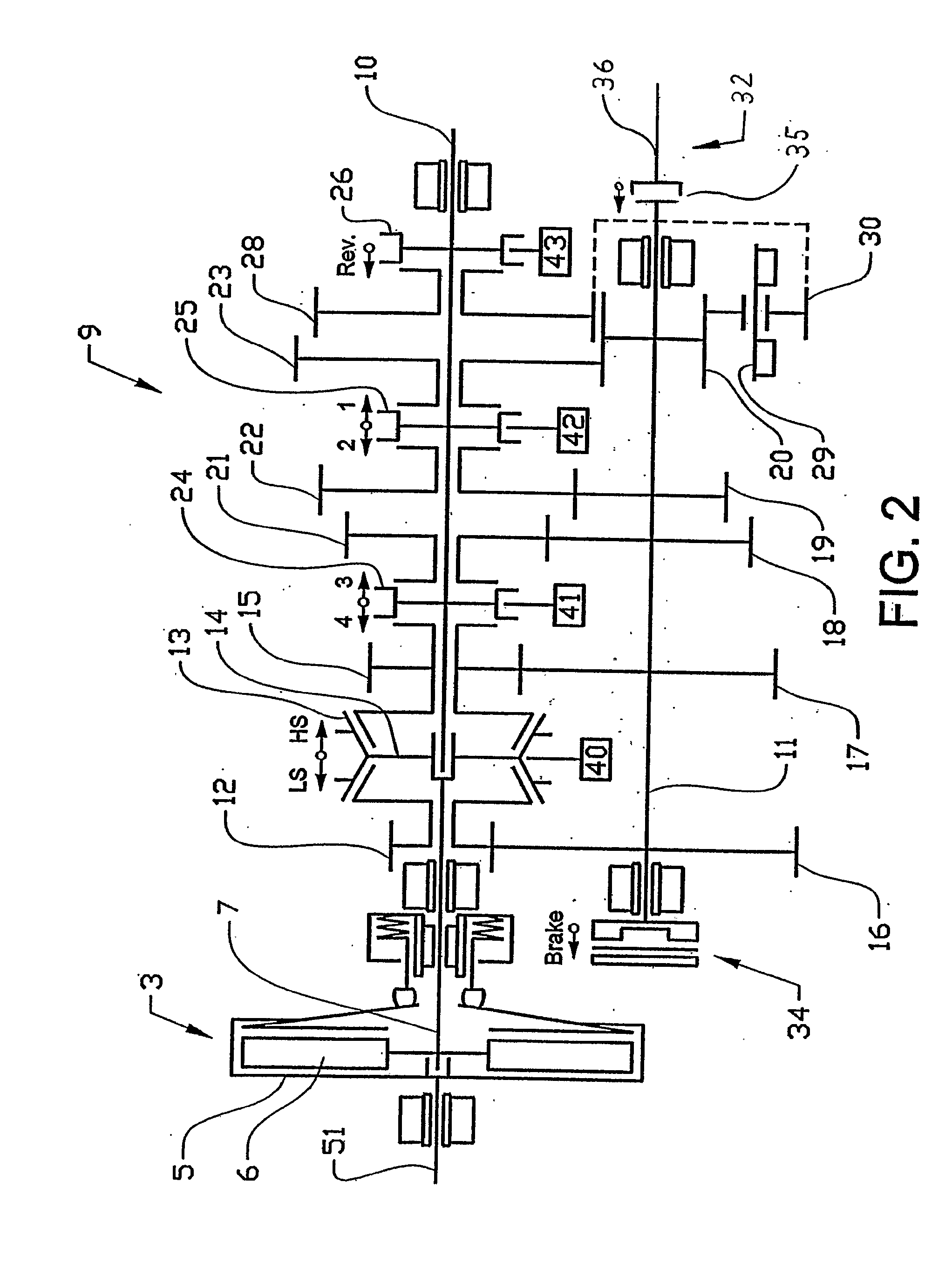
[0033] As is most clearly apparent from FIG. 2, a gear wheel 12 is rotatably mounted on the input shaft 7 such that it can be locked on the shaft with the aid of a coupling sleeve 13, which is provided with synchronizing members and is mounted in a non-rotatable yet axially displaceable manner on a hub 14 non-rotatab...


PUM


Abstract

An automatic gearshifting process and/or disengagement process of a coupling-dependent power take off for a vehicle with the power take off engaged and when the vehicle is in motion. The power tapping at the power take off is minimized before a gearshift and/or disengagement of the claw clutch of the power take off takes place. One advantage is that gearshifting can be realized with engaged coupling-dependent power take off. Comfort is increased and coupling teeth wear is minimized, whilst, at the same time, a gear and the claw clutch of the power take off are able to be securely disengaged.

Description

BACKGROUND AND SUMMARY [0001] The present application is a continuation of International Application No. PCT / SE2004 / 001926, filed Dec. 17, 2004, which claims priority to SE 0303446-9, filed Dec. 17, 2003, both of which are incorporated by reference. [0002] The present invention relates to a process for use in a motor vehicle. The processes relate to an automatic gearshifting process with the vehicle in driving mode and a simultaneously engaged coupling-dependent power take off and automatic disengagement of said power take off with the vehicle in driving mode. [0003] The power take off is disposed on the transmission of the vehicle. [0004] In order rationally to be able to handle the load on a goods vehicle, load handling equipment is required. The most common examples of such equipment are tipper and crane. Other commonly found examples are load changer, garbage handling unit, rotary cement mixer, rinsing unit, refrigeration unit, pumping equipment for various types of liquids and ...

Claims


Application Information

Patent Timeline
IPC IPC(8): G06F17/00B60K17/28B60W10/06B60W10/10B60W10/30B60W30/18F16H63/40
CPCB60K17/28B60K2741/225B60W10/11B60W10/30Y10T74/19288B60W30/19F16H2306/44F16H2306/46Y10T477/675B60W30/1888B60W10/02B60W10/10B60W30/1819
Inventor STEEN, MARCUSKARLSSON, SVANTELAURI, ERIK
Owner VOLVO LASTVAGNAR AB
Why Eureka
Try Eureka