Multi-axis, processor-controlled, toolhead positioner

a technology of processor control and toolhead positioner, which is applied in the direction of programmed manipulators, other manufacturing equipment/tools, manufacturing tools, etc., can solve the problems of limited use potential, and achieve the effects of small size, less cost, and light weigh

Inactive Publication Date: 2006-11-02
PRECISION SPHERICAL
View PDF26 Cites 66 Cited by
  • Summary
  • Abstract
  • Description
  • Claims
  • Application Information

AI Technical Summary

Benefits of technology

[0029] It is an object of the present invention to provide a computer numerically-controlled (CNC) positioning device and platform for numerous types of toolhead assemblies.
[0030] It is an object of the present invention to offer a platform for a smaller, less expensive, lighter, and easier-to-use CNC router and milling machine.
[0031] It is an object of the present invention to offer a platform, outfitted with the appropriate toolhead assembly, to automatically and rapidly size and machine a sphere to a precise diameter, using only two degrees of freedom, that of two perpendicular rotational axes.
[0032] It is an object of the present invention to offer a platform, outfitted with the app

Problems solved by technology

As a toolhead positioning device, the potential uses are limited only by the

Method used


Image

  • Multi-axis, processor-controlled, toolhead positioner
  • Multi-axis, processor-controlled, toolhead positioner
  • Multi-axis, processor-controlled, toolhead positioner

Examples


Embodiment Construction

(1) Preferred Embodiment

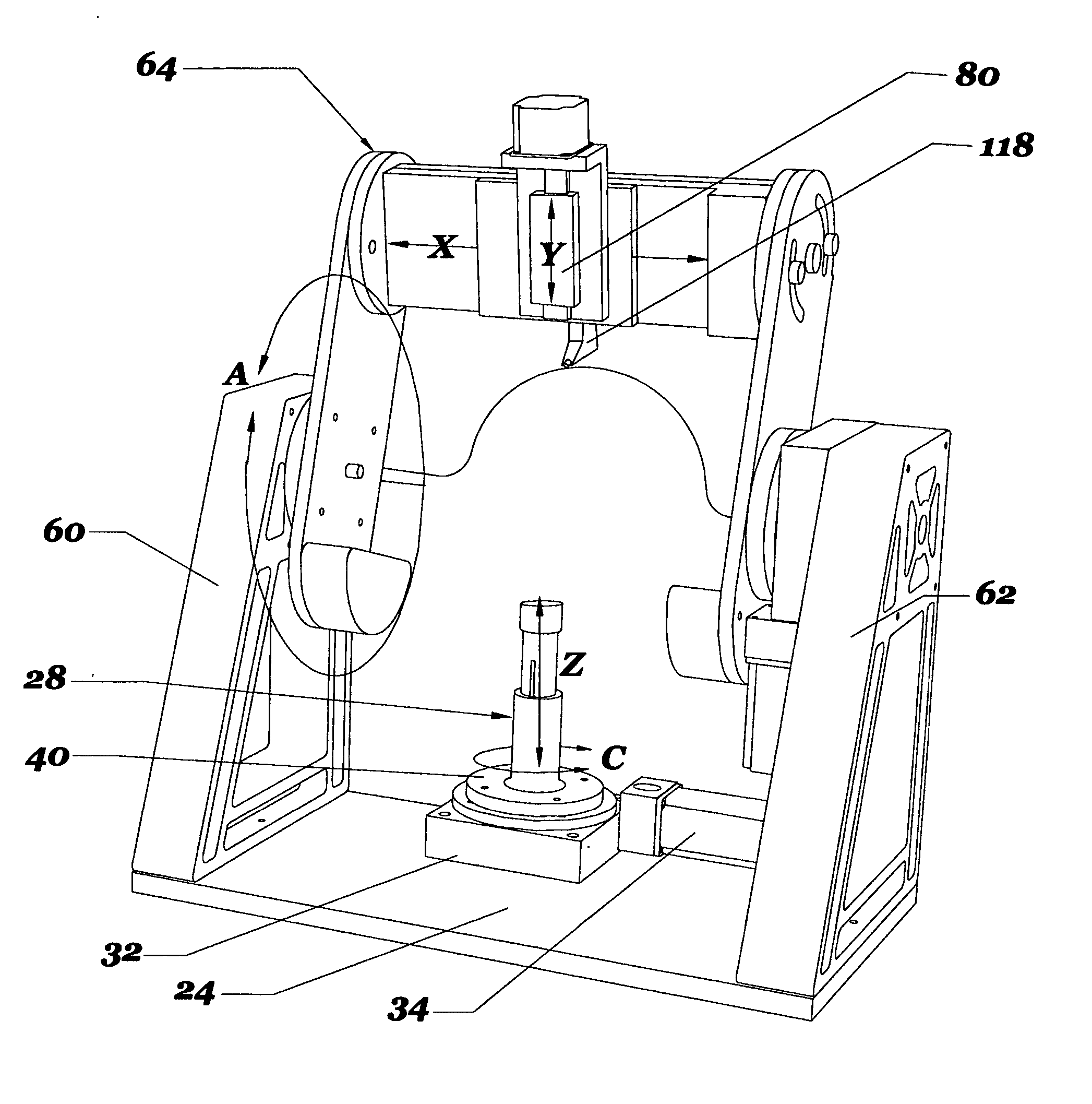
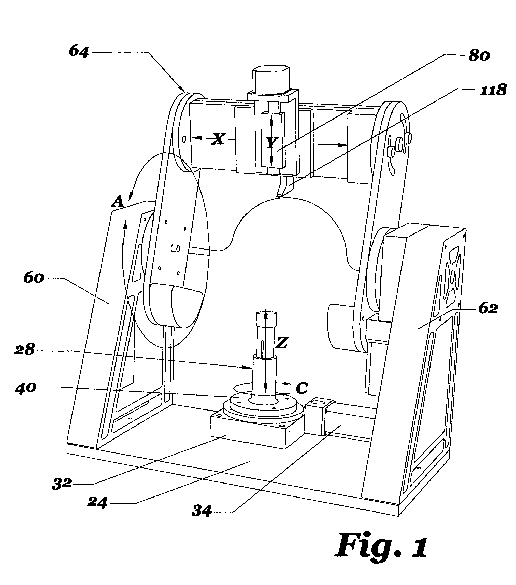
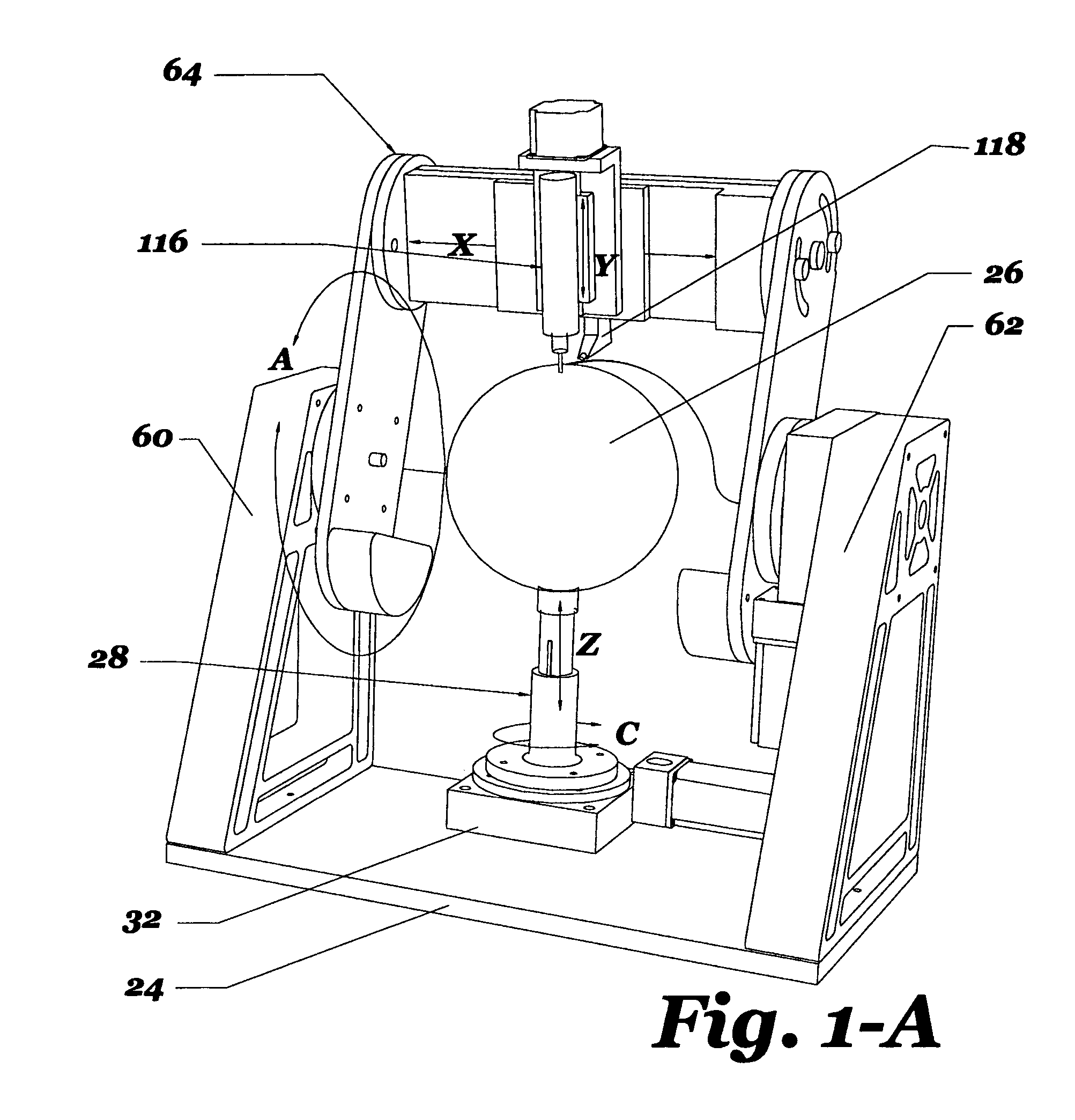
[0126] A preferred embodiment of the multi-axis, processor-controlled, toolhead positioning device is illustrated in FIG. 1 and FIG. 2. FIG. 1 shows a perspective view of the front of the invention illustrating a workpiece mount assembly 28, an elevated gantry 64, and the linear and rotational axes of movement. FIG. 2 shows a perspective view of the rear of invention again illustrating the workpiece mount assembly 28, but showing the gantry 64 in a lowered position. As the invention is described, directions such as right, left, up, down, front, and back are as viewed by an individual standing in front of and facing the invention. The linear and rotational axes of movement referred to throughout this specification are described in greater detail in the summary.

[0127] The major components of the multi-axis, processor-controlled, toolhead positioning device are illustrated in FIG. 1. They comprise the following: a base plate 24, a rotating and elevating workpi...


PUM

PropertyMeasurementUnit
Angleaaaaaaaaaa

Abstract

A multi-axis, computerized numerically-controlled (CNC) toolhead positioning device with six degrees of freedom of movement while utilizing only five axes of movement, comprising a rotating workpiece mount assembly (28) and a rotating gantry (64) with a mounted toolhead assembly base (80). Perpendicular rotational axes about a mounted workpiece (26) provide the capability to perform specific toolhead operations on the arcuate surface of the workpiece (26), subject to the type of mounted toolhead assembly. The computer (120) uses CNC software to integrate operator instructions, machining operations, and the sequence of operations into an automatic and coherent machining package.

Description

BACKGROUND OF THE INVENTION [0001] (1) Field of Invention [0002] The present invention relates generally to devices for the accurate and repeated automatic or robotic control of the movement and positioning of a toolhead relative to the surface of a workpiece for carrying out computer-controlled programmed instructions for manufacturing operations. [0003] (2) Description of Prior Art [0004] The acronyms CNC and CAM stand respectively for Computer(ized) Numerical(ly) Control(led) and Computer Aided Manufacturing, and refers specifically to the computer control of machine tools for the purpose of (repeatedly) manufacturing complex parts in metal as well as other materials. [0005] The introduction of CNC machines radically changed the manufacturing industry. Curves were as easy to cut as straight lines, complex 3-D structures were relatively easy to produce, and the number of machining steps that required human action diminished drastically. [0006] In a production environment, all of t...

Claims


Application Information

Patent Timeline
IPC IPC(8): B23P23/00
CPCB23Q1/012B23Q1/4842B25J9/026B25J9/04Y10T409/307728Y10T29/50Y10T409/308288Y10T409/309576Y10T409/305488Y10T29/5107Y10T409/307672Y10T29/51Y10T409/305656Y10T408/93B23Q1/015
Inventor PENICK, WILLIAM ARTHURFOMEY, ROBERT ALLEN
Owner PRECISION SPHERICAL
Why Eureka
Try Eureka