Boiler tube position retainer assembly

a technology of retainer assembly and boiler tube, which is applied in the direction of boiler flue/fire tube, boiler supporting/setting arrangement, lighting and heating apparatus, etc., can solve the problems of small tolerance for expansion and contraction of boiler tube, inability to maximize heat transfer, and debris caught between boiler tub

Active Publication Date: 2006-11-02
RETTIG MARK +2
View PDF11 Cites 7 Cited by
  • Summary
  • Abstract
  • Description
  • Claims
  • Application Information

AI Technical Summary

Benefits of technology

[0005] When water is pumped through the boiler tubes, the boiler becomes a powerful steam generator. Water enteri...

Problems solved by technology

Although these metal boiler tubes are positioned to maximize heat transfer, debris may get caught between the boiler tubes if they are spaced too close together.
If boiler tubes are positioned too far apart, heat transfer may not be maximized.
When the two pieces of this assembly are properly positioned, there is very little tolerance for expansion and contraction of the boiler tubes, thereby placing stress on the tubes at the weld connection.
When the stress is too great, the boiler tubes will break, rupture or leak, causing leakage and eventual shut down of the boiler for an unscheduled repair.
The clip is generally stronger than the boiler tubing, and therefore tube failure occurs before clip failure in most cases.
Again, problems similar to the example in FIG. 1 are also present.
There is very little tolerance for expansion and contraction of the boiler tubes 20 and 21, putting the stress on the welds, again resulting in tube failure prior to clip failure....

Method used


Image

  • Boiler tube position retainer assembly
  • Boiler tube position retainer assembly
  • Boiler tube position retainer assembly

Examples


Embodiment Construction

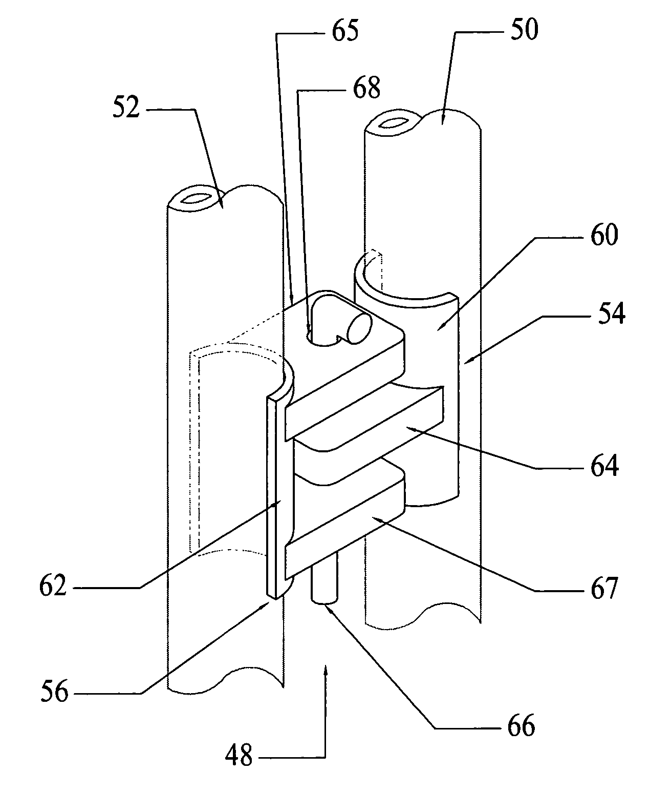
[0019] The present invention concerns a saddle clip styled, boiler tube position retainer assembly for securing boiler tubes in power boilers. The present invention supports and stabilizes the boiler tubes while allowing for slight vertical and horizontal movements. The present invention also concerns a method for positioning and stabilizing boiler tubes in power boilers, while allowing for some vertical and horizontal movement during expansion and contraction without damage to tube sheet or boiler tubes.

[0020] The tube assembly device of the present invention maintains spacing for proper heat transfer and avoids tubing wall removal should weld failure occur, thereby decreasing leakage of boiler tubes, shut down time and unscheduled down time for inspections and repairs. Productivity of the boilers is increased and maintenance costs are decreased. In the event of excess stress on the positioning assembly, the boiler tube position retainer assembly of the present invention allows fo...


PUM


Abstract

The tube assembly device of the present invention maintains spacing for proper heat transfer and avoids tubing wall removal should weld failure occur, thereby decreasing leakage of boiler tubes, shut down time and unscheduled down time for inspections and repairs. Productivity of the boilers is increased and maintenance costs are decreased. In the event of excess stress on the positioning assembly, the retainer assembly of the present invention allows for failure points to occur on the boiler tube position retainer assemblies rather than on the boiler tubes themselves.

Description

[0001] CROSS REFERENCE TO RELATED APPLICATION [0002] This patent application is the utility application of the previously filed U.S. Provisional Applications Number 60 / 594,691, entitled “Boiler Tube Position Retainer Assembly” filed on Apr. 28, 2005. The Provisional Application is incorporated herein by reference.BACKGROUND OF INVENTION [0003] The present invention concerns a boiler tube position retainer assembly for stabilizing and supporting boiler tubes in boilers. The present invention more particularly concerns boiler tube clips for use in large industrial boilers. Primary or secondary furnace superheaters and reheaters function as important industrial power sources throughout the world. Power boilers, which may be one hundred feet in width or more with boiler tubes of over forty feet in length, are used as industrial power generators in various applications. For example, industrial power boilers may be used as steam generators in paper mills or power plants. [0004] Similar to...

Claims


Application Information

Patent Timeline
IPC IPC(8): F22B1/00
CPCF22B37/205
Inventor RETTING, MARK W.CLIFTON, SAMUEL W.SULLIVAN, MICHAEL D.
Owner RETTIG MARK
Why Eureka
Try Eureka