Mode transition control system for hybrid vehicle

a control system and hybrid technology, applied in the direction of electric propulsion mounting, machines/engines, transportation and packaging, etc., can solve the problems of inertia and engine friction, and achieve the effect of preventing adverse effects on the driver's feeling

Inactive Publication Date: 2006-11-02
NISSAN MOTOR CO LTD
View PDF9 Cites 48 Cited by
  • Summary
  • Abstract
  • Description
  • Claims
  • Application Information

AI Technical Summary

Benefits of technology

[0004] It is an object of the present invention to provide a mode transition control system for a hybrid vehicle configured to shift smoothly from a motor regenerative braking to an engine braking, and thereby to prevent from affecting a driver's feeling adversely.

Problems solved by technology

Accordingly, it is problematical to generate larger shock by the inertia and the friction by the engine when the disengaged clutch is reengaged in accordance with the request of the shift.

Method used


Image

  • Mode transition control system for hybrid vehicle
  • Mode transition control system for hybrid vehicle
  • Mode transition control system for hybrid vehicle

Examples


Embodiment Construction

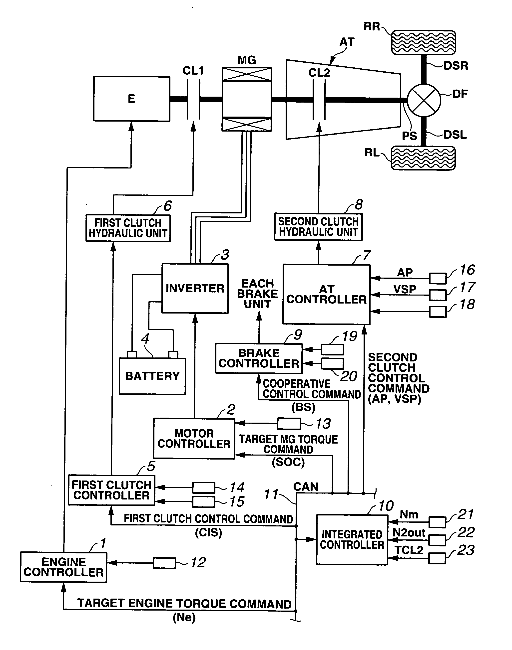
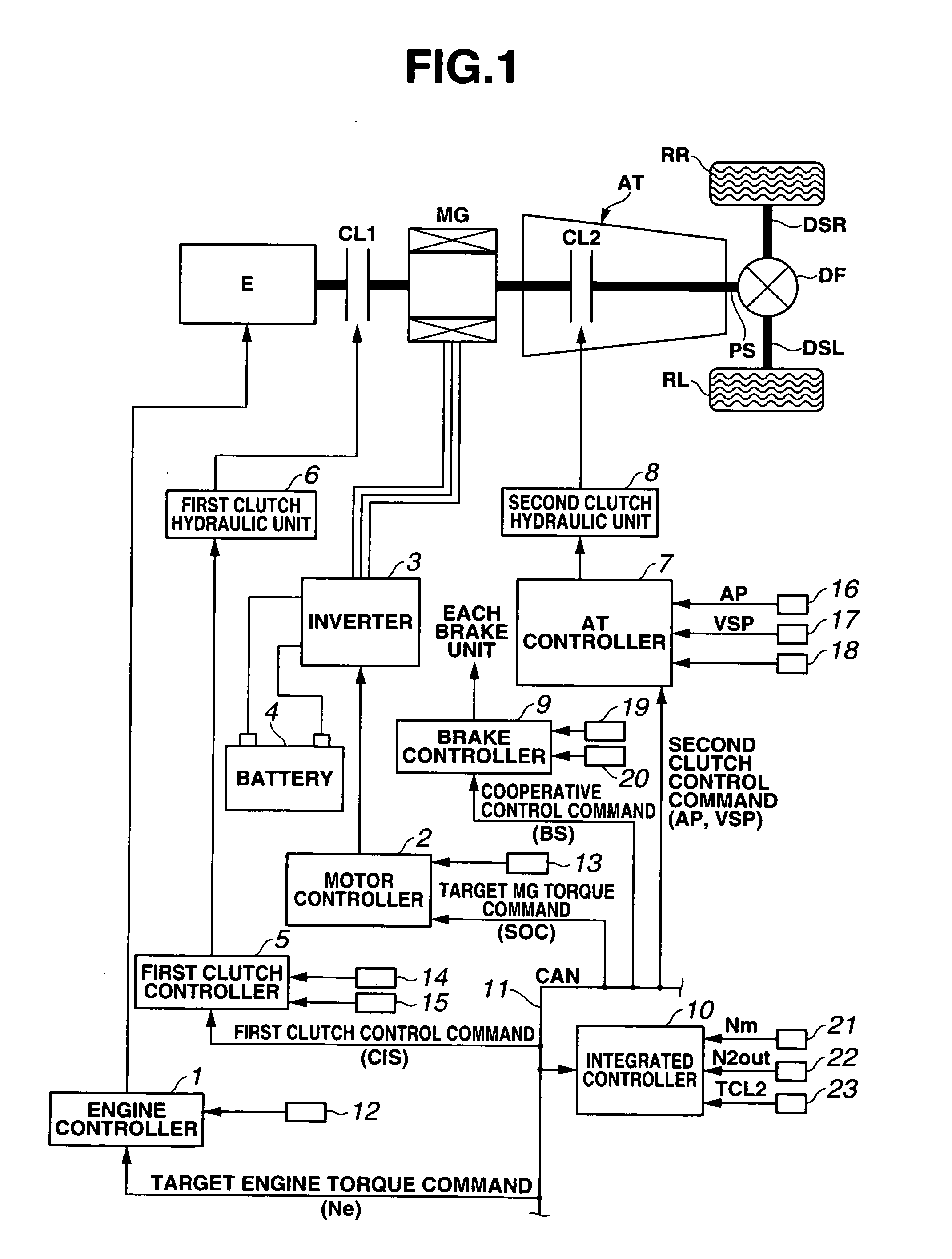
[0011]FIG. 1 shows an overall view showing a rear-wheel drive hybrid vehicle equipped with a regenerative braking control system according to an embodiment of the present invention. The drive system for the hybrid vehicle includes an engine E, a motor generator MG, a first clutch CL1, a second clutch CL2, an automatic transmission AT, a propeller shaft PS, a differential DF, a left drive shaft DSL, a right drive shaft DSR, a left rear wheel (driving wheel) RL, and a right rear wheel (driving wheel) RR.

[0012] Engine E is a gasoline engine or a diesel engine. Valve openings of throttle valves of engine E and so on are controlled in accordance with a control command from an engine controller 1 described later.

[0013] Motor generator MG is a synchronous motor generator including a rotor in which permanent magnets are embedded, and a stator provided with stator coils. Motor generator MG is controlled by being applied with three-phase alternative current generated by an inverter 3 in acc...


PUM


Abstract

A hybrid vehicle mode transition control apparatus includes a hybrid drive system having a first clutch disposed between an engine and a motor generator, and a second clutch disposed between the motor generator and wheels; an engine braking request judging section configured to judge whether a request of an engine braking is present during a motor regenerative braking performed by the motor generator, and a mode transition control section configured to perform a mode transition control of the hybrid drive system in accordance with a transition request. The mode transition control apparatus is configured to decrease a torque capacity of the second clutch being in an engaged state in response to the judgment that the request of the engine braking is present, and to bring the first clutch from a disengaged state to the engaged state to shift to the engine braking.

Description

BACKGROUND OF THE INVENTION [0001] The present invention relates to a mode transition control system for a hybrid vehicle with a hybrid drive system including a first clutch disposed between an engine and a motor generator, and a second clutch disposed between the motor generator and driving wheels. [0002] Japanese Patent Application Publication No. 2002-144921 shows a control system for a hybrid vehicle including an engine, a motor generator used for drive, start, and power generation, and a clutch disposed between the engine and the motor generator. This control system eliminates loss of a regenerative quantity of electric energy by engine friction during a regenerative braking performed by the motor generator, by disconnecting the engine with a drivetrain. This control system can ensure the regenerative quantity fully and efficiently. SUMMARY OF THE INVENTION [0003] The above-mentioned control apparatus is arranged not to transmit the engine friction by disengagement of the clutc...

Claims


Application Information

Patent Timeline
Patent Type & Authority Applications(United States)
IPC IPC(8): B60K1/00B60K6/48B60K6/547B60K17/02B60K17/04B60L50/16B60W10/02B60W10/04B60W10/06B60W10/08B60W10/18B60W20/00F02D29/00F02D29/02F02D29/06F16H59/42F16H61/02F16H61/21F16H61/68
CPCB60K6/48B60K6/54B60W10/02B60W10/08Y02T10/6221B60W30/18127B60W30/18136F16H61/21B60W20/00B60L7/10B60L7/18B60L15/2009Y10S903/906Y02T10/72B60L50/15Y02T10/62Y02T10/64Y02T10/7072B60W2710/025
Inventor HIDAKA, TERUMASA
Owner NISSAN MOTOR CO LTD
Why Eureka
Try Eureka