
Solenoid-operated fluid valve and assembly incorporating same

a solenoid-operated, fluid valve technology, applied in the direction of valve operating means/release devices, functional valve types, liquid transfer devices, etc., can solve the problems of large volume of pneumatic counterparts, insufficient responsiveness to the high-speed opening and closing sequence required for modern adhesive-dispensing equipment, and insufficient heat buildup of coils. , to achieve the effect of reducing coil heat buildup, increasing the duty cycle of the valve, and enhancing magnetic flux

Inactive Publication Date: 2006-11-02
VALCO CINCINNATI
View PDF25 Cites 9 Cited by
  • Summary
  • Abstract
  • Description
  • Claims
  • Application Information

AI Technical Summary

Benefits of technology

[0009] According to yet another aspect of the invention, a method of dispensing a fluid through a valve is disclosed. The method includes configuring a fluid tube to have a fluid inlet and a fluid outlet. In addition, the construction of the valve is such that it includes an outer surface and an inner surface. The inner surface defines a fluid chamber inside the valve body. As with the previous aspects, a coil is wound directly around at least a portion of the periphery of the outer surface. The method also includes moveably disposing a plunger within the fluid chamber such that it is biased in a closed position. In this way, when electric current is passed through the coil winding, the plunger overcomes the bias to move to an open position, thereby allowing fluid from the fluid supply to pass through the fluid outlet end of the valve body.
[0010] Optionally, the method further includes cooling the solenoid with the fluid. In one form, a substantially linear flowpath allows fluid delivered therethrough to reduce coil heat buildup, thereby increasing the duty cycle of the valve. In addition, a housing can be used to package the valve in a widthwise relatively thin profile (for example, no greater than fifteen millimeters wide). The method may further comprise placing a stop adjacent one of the fluid inlet and outlet to limit travel of the plunger in the fluid chamber. In another option, the coil winding can be isolated from the fluid. A switch may be included disposed on the valve such that upon engagement of the switch by an operator, the valve is purged of residual fluid. The method may further include placing the fluid tube within a frame such that upon formation of the magnetic flux, the magnetic flux is enhanced in the fluid tube by its proximity to the frame. In addition, a stroke between the plunger and the stop can be adjusted.

Problems solved by technology

Traditional pneumatic-actuated valves, which rely on a supply of compressed air to reciprocally move a plunger back and forth in a fluid chamber to selectively open and close the valve, are not sufficiently responsive to high speed opening and closing sequences required for modern adhesive-dispensing equipment.
Unfortunately, such solenoid valves, which rely on electric current passing through a wound coil to develop an electromagnetic field with which to move a magnetically-susceptible plunger, are larger than their pneumatic counterparts.
This is disadvantageous in that adhesive dispensing valves are frequently arranged in a side-by-side (also called stacked) array, and any increase in size would be incompatible with the tight dispensing patterns required of a stacked configuration.
Further, many machines where such valves are installed have tight space restrictions, making large solenoids impossible to install.

Method used


Image

  • Solenoid-operated fluid valve and assembly incorporating same
  • Solenoid-operated fluid valve and assembly incorporating same
  • Solenoid-operated fluid valve and assembly incorporating same

Examples


Embodiment Construction

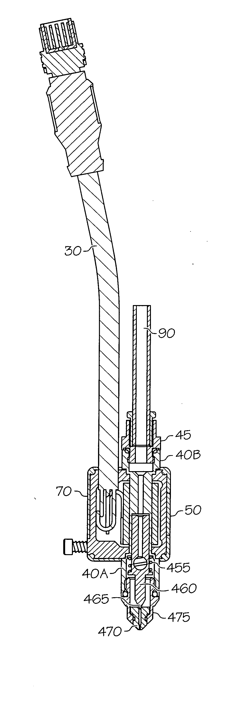
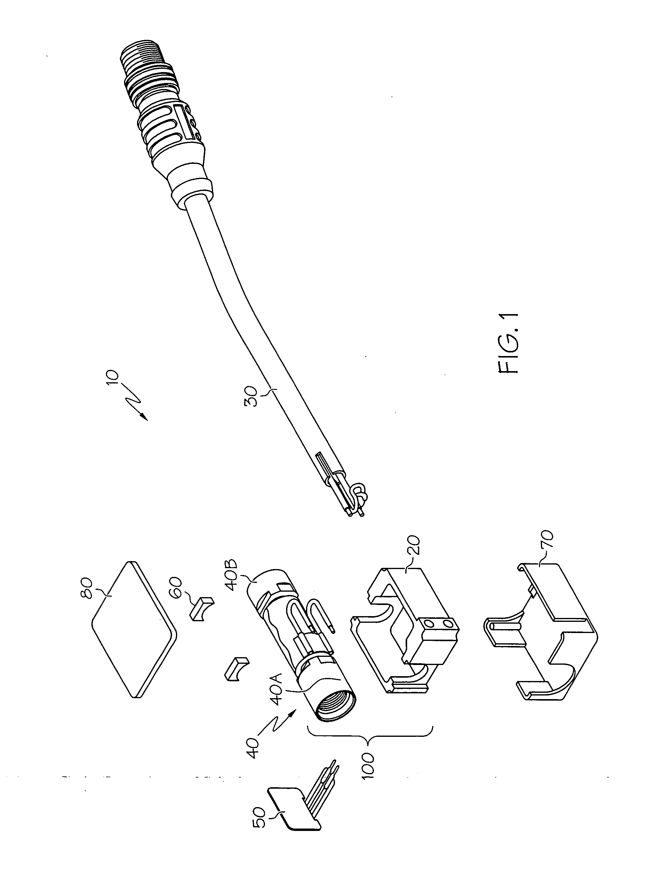
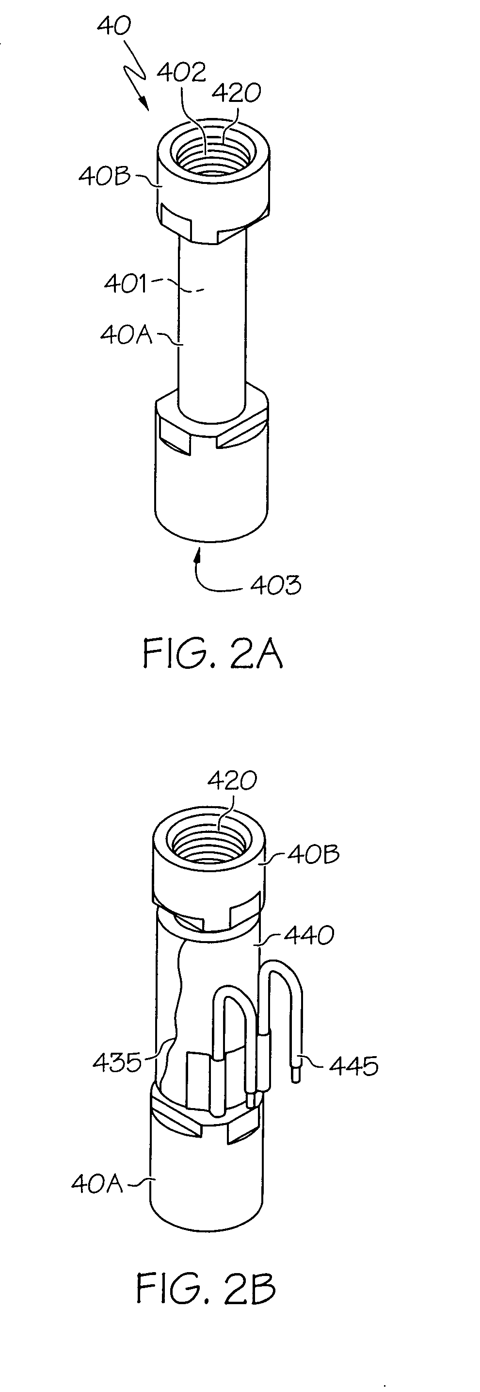
[0022] Referring first to FIG. 1, an exploded view of the solenoid-operated fluid valve assembly 10 is shown. Assembly 10 includes a coil frame 20 that fits within an outer casing 70. Coil frame 20 is shaped to accept a fluid tube 40 therein, and is made of a material that facilitates the conduction of a magnetic flux. In the present context, the term “assembly” is used to designate the construction of individual parts, and may be used interchangeably to refer to the assembled version of a valve (which is made from a valve body 100 made up of fluid tube 40, frame 20, coil 435 and valve internals, such as plunger 460 and biasing spring 455) as well as the entire solenoid-operated fluid valve assembly 10; the usage will be apparent from the context. An electric power supply (shown in the form of cable 30) is used to provide current flow through coils (discussed in more detail below) that are wound around and make up a part of a valve body 100 based on fluid tube 40. A switch 50 is pla...


PUM


Abstract

A solenoid-operated valve and valve assembly. The valve may be made from a fluid tube that has a magnetizable plunger or armature movably positioned in the body. A coil of wire is directly wound to the fluid tube, thereby reducing the air gap between magnetic flux path and plunger to increase the magnetic force imparted to the plunger. Winding the coil to the valve body removes the need for a separate sleeve or bobbin, and additionally allows for tighter spacing and reduced air gap, thereby increasing magnetic flux by allowing more coil turns and closer coil spacing to the plunger. In one form, the valve is packaged into a narrow (for example, 15 millimeters wide) configuration for close valve-to-valve stackable centers, thereby allowing multiple valves to be placed side-by-side for adhesive or related fluid dispensing applications.

Description

CROSS REFERENCE [0001] This application claims the benefit of the filing date of U.S. Provisional Application No. 60 / 676,748, filed May 2, 2005.BACKGROUND OF THE INVENTION [0002] The present invention relates generally to a fluid valve, and more particularly to a compact solenoid-controlled valve for use in dispensing viscous fluids. [0003] Adhesives and other high-viscosity fluids require high-speed valves for proper operation. Traditional pneumatic-actuated valves, which rely on a supply of compressed air to reciprocally move a plunger back and forth in a fluid chamber to selectively open and close the valve, are not sufficiently responsive to high speed opening and closing sequences required for modern adhesive-dispensing equipment. [0004] More recently, solenoid-operated valves have been developed to overcome this limitation. Unfortunately, such solenoid valves, which rely on electric current passing through a wound coil to develop an electromagnetic field with which to move a m...

Claims


Application Information

Patent Timeline
IPC IPC(8): B67D3/00
CPCB05B1/3053F16K31/0655F16K31/0651B05C5/0225F16K21/04F16K31/02
Inventor PARKS, RANDOLPH S.PROKOP, RAYMOND A.
Owner VALCO CINCINNATI
Learn More