
Activating a phase in a multiphase DC/DC converter without disturbing the output voltage

a multi-phase dc/dc converter and output voltage technology, applied in the direction of dc-dc conversion, power conversion systems, ac networks with different sources at the same frequency, etc., can solve the problems of reducing overall efficiency, affecting the operation of the system, and increasing output, so as to increase the duty cycle of the first ripple capacitor, increase the duty cycle of the second ripple capacitor, and reduce the duty cycle of the first ripple capacitor

Inactive Publication Date: 2006-04-04
INTERSIL INC
View PDF6 Cites 38 Cited by
  • Summary
  • Abstract
  • Description
  • Claims
  • Application Information

AI Technical Summary

Benefits of technology

[0015]A method of activating a phase in a multiphase DC / DC converter according to an embodiment of the present invention is disclosed. The multiphase DC / DC converter includes a first phase circuit providing a first PWM signal and a second phase circuit providing a second PWM signal and that is selectively enabled. The method includes receiving a phase enable signal and enabling operation of the second phase circuit, sensing output current of the multiphase DC / DC converter, converting sensed output current to an adjust signal, and reducing duty cycle of the first PWM signal while increasing duty cycle of the second PWM signal based on the adjust signal.

Problems solved by technology

The temporary increase in output voltage, however, often had deleterious effects on the system, and reduced overall efficiency.
The current feedback loop was (and potentially still is) relatively slow so that the relative current levels were imbalanced for a significant period of time, which further reduced overall efficiency.

Method used


Image

  • Activating a phase in a multiphase DC/DC converter without disturbing the output voltage
  • Activating a phase in a multiphase DC/DC converter without disturbing the output voltage
  • Activating a phase in a multiphase DC/DC converter without disturbing the output voltage

Examples


Embodiment Construction

[0022]The following description is presented to enable one of ordinary skill in the art to make and use the present invention as provided within the context of a particular application and its requirements. Various modifications to the preferred embodiment will, however, be apparent to one skilled in the art, and the general principles defined herein may be applied to other embodiments. Therefore, the present invention is not intended to be limited to the particular embodiments shown and described herein, but is to be accorded the widest scope consistent with the principles and novel features herein disclosed.

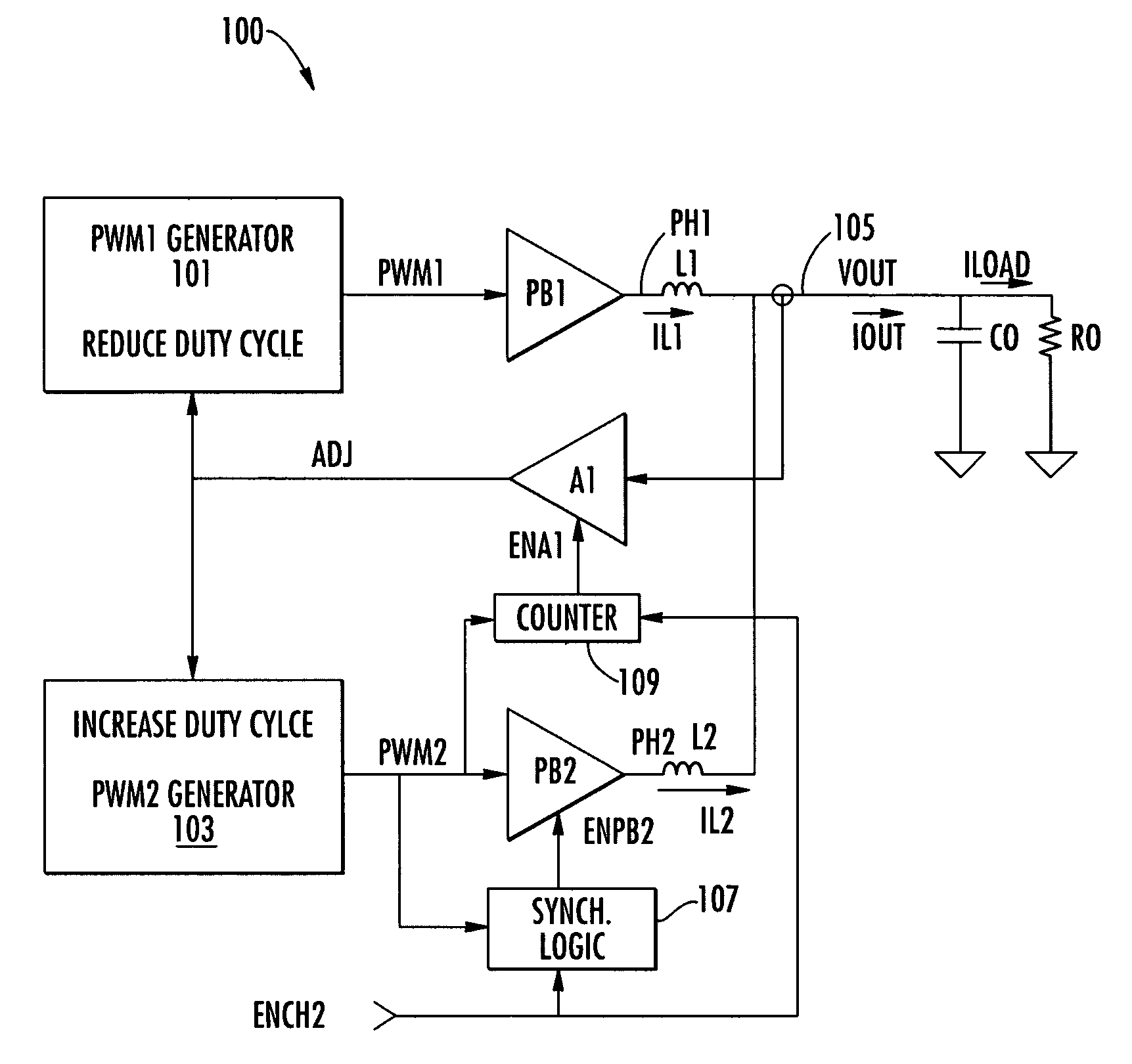
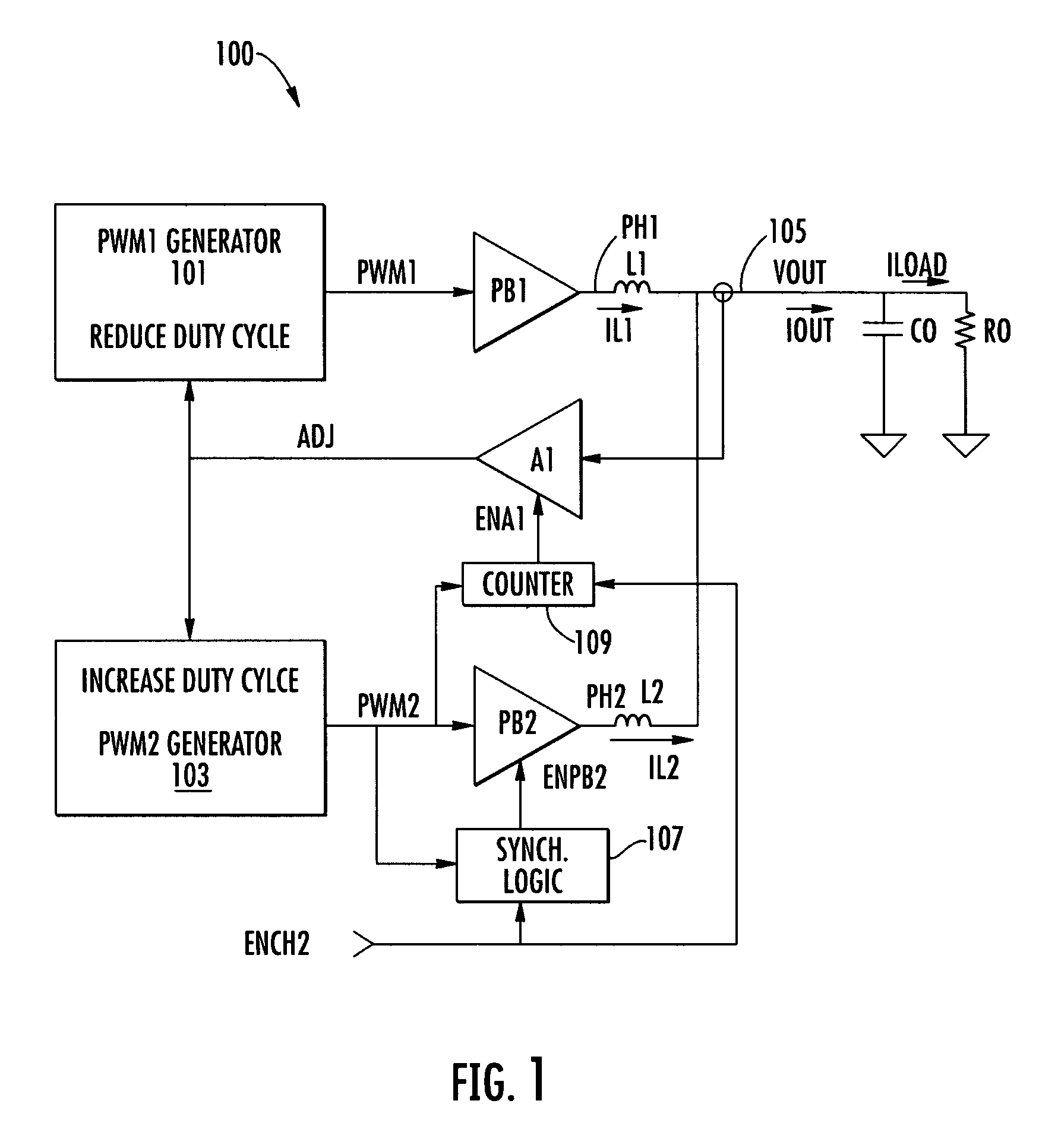
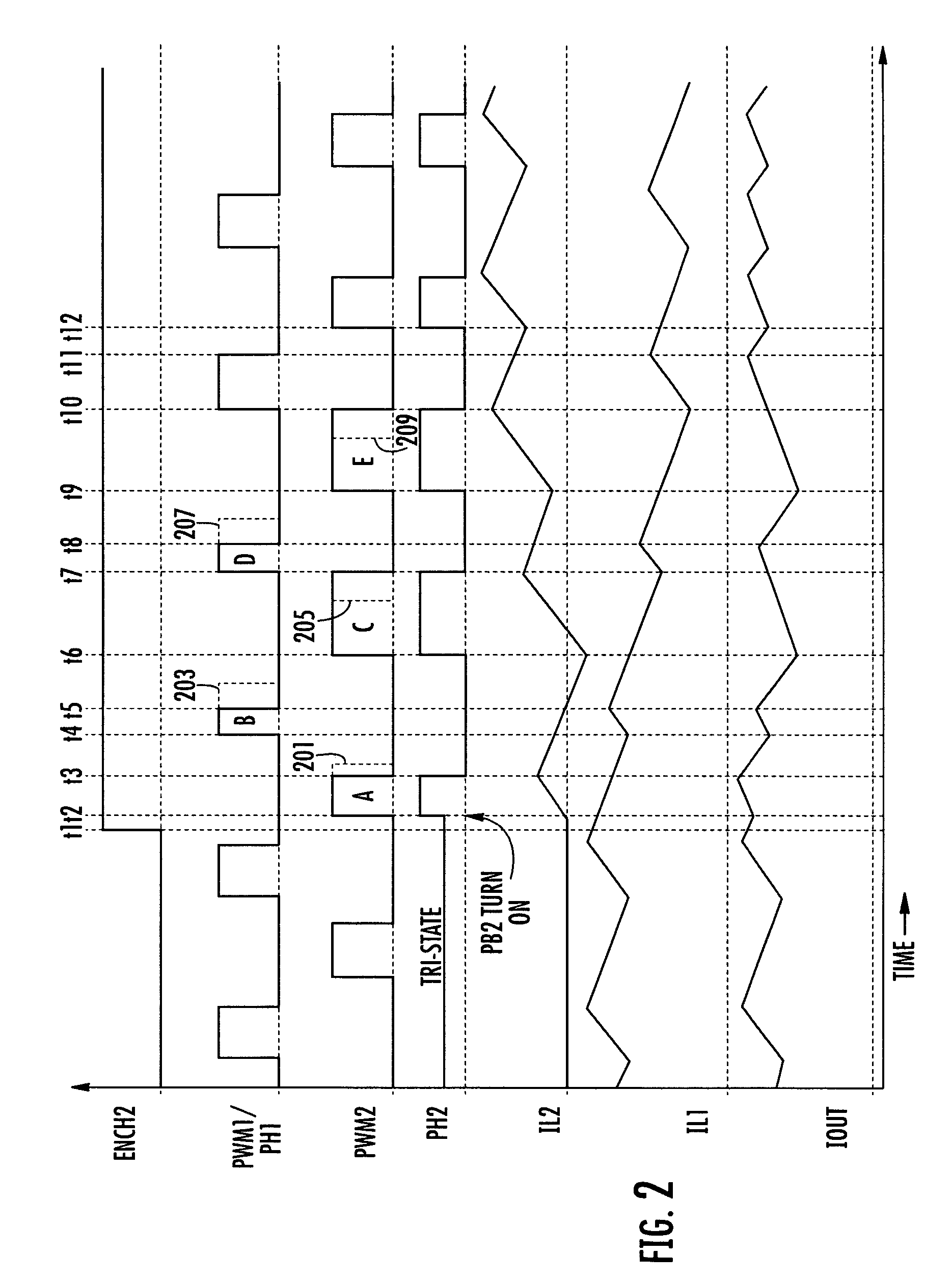
[0023]FIG. 1 is a simplified schematic diagram of a multiphase DC / DC converter 100 including a phase activation control system implemented according to an exemplary embodiment of the present invention. The multiphase DC / DC converter 100 includes a PWM 1 generator 101 asserting a first pulse-width modulation (PWM) signal PWM 1 and a PWM2 generator 103 asserting a second PWM sign...


PUM


Abstract

A phase activation control system for a multiphase DC / DC converter including an amplifier circuit and enable logic. The converter includes a first phase circuit providing a first PWM signal and has a reduce input for reducing duty cycle of the first PWM signal. The converter further includes a second phase circuit providing a second PWM signal and having an enable input and an increase input for increasing duty cycle of the second PWM signal. The amplifier circuit has an enable input, a current sense input for sensing output current of the converter and an output providing an adjust signal. The adjust signal is provided to the reduce input of the first phase circuit and to the increase input of the second phase circuit. The enable logic receives a phase enable signal and enables the amplifier circuit and the second phase circuit.

Description

CROSS-REFERENCE TO RELATED APPLICATIONS[0001]This application claims the benefit of U.S. Provisional Application No. 60 / 624,786 filed on Nov. 3, 2004, which is herein incorporated by reference for all intents and purposes.BACKGROUND OF THE INVENTION[0002]1. Field of the Invention[0003]The present invention relates to multiphase DC / DC converters, and more particularly to adding a phase in a multiphase DC / DC converter without disturbing the output voltage.[0004]2. Description of the Related Art[0005]Multiphase DC / DC converters distribute current to a load among multiple phases or channels to provide increased output power and to improve efficiency at high load levels. Many electronic devices include a low-power or reduced power mode to conserve energy or battery power. The multiphase converter becomes less efficient at lower power levels while all phases remain active, so that it is desired to shut down one or more phases during lower power levels. Control logic of the device determin...

Claims


Application Information

Patent Timeline
Patent Type & Authority Patents(United States)
IPC IPC(8): G05F1/00
CPCH02M3/1584H02M3/157
Inventor KLEINE, JOHN S.JOCHUM, THOMAS A.
Owner INTERSIL INC
Learn More