
Probe card configuration for low mechanical flexural strength electrical routing substrates

a technology of electrical routing substrate and mechanical flexural strength, which is applied in the direction of semiconductor/solid-state device testing/measurement, coupling device connection, instruments, etc., can solve the problems of increasing the size and complexity of the test system probe card for testing the wafer, increasing the bending load of the probe card, and reducing the wafer size. , to achieve the effect of reducing the amount of force, preventing cracking or flexing of a larger substrate, and increasing the length of the extension

Inactive Publication Date: 2006-11-02
FORMFACTOR INC
View PDF13 Cites 29 Cited by
  • Summary
  • Abstract
  • Description
  • Claims
  • Application Information

AI Technical Summary

Benefits of technology

The modified support configuration effectively reduces substrate deflection and stress, maintains precise leveling, and prevents mechanical damage to low flexural strength substrates, ensuring reliable electrical connections and improved testing accuracy.

Problems solved by technology

With an increased size of wafers, a corresponding increase in size and complexity of test system probe cards for testing the wafers occurs.
The larger probe cards with added probes typically result in more bending loads on the probe cards.
In the past, wafers have been smaller and the number of spring probes on a space transformer have been limited.
With space transformers having a larger surface area and more pins to test larger wafers requiring fewer touch downs, the space transformer substrates may crack or flex out of a level planar shape due to either forces applied from the interposer, or bending forces resulting from probing.
The load support member can be machined into the frame, but the electrical insulation properties and flexibility of changing the load support contact location using the flexible membrane will not be provided.

Method used


Image

  • Probe card configuration for low mechanical flexural strength electrical routing substrates
  • Probe card configuration for low mechanical flexural strength electrical routing substrates
  • Probe card configuration for low mechanical flexural strength electrical routing substrates

Examples


Embodiment Construction

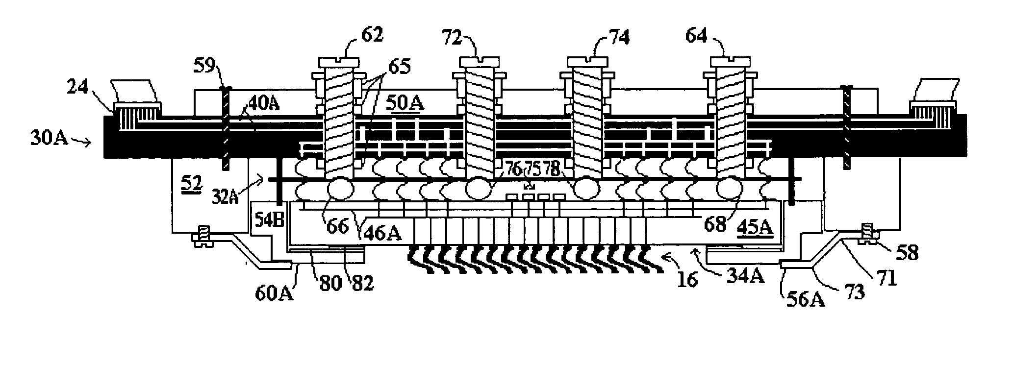
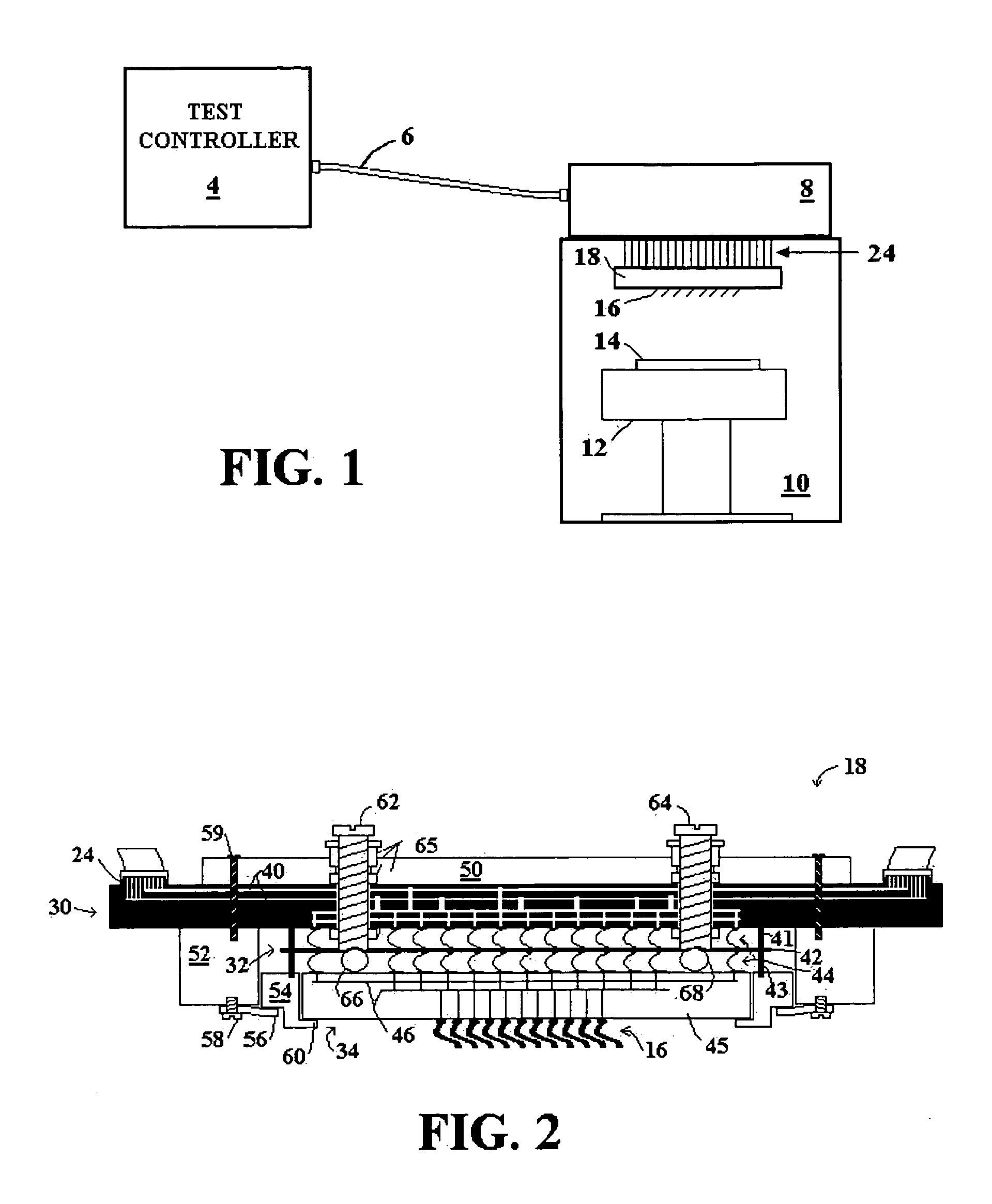
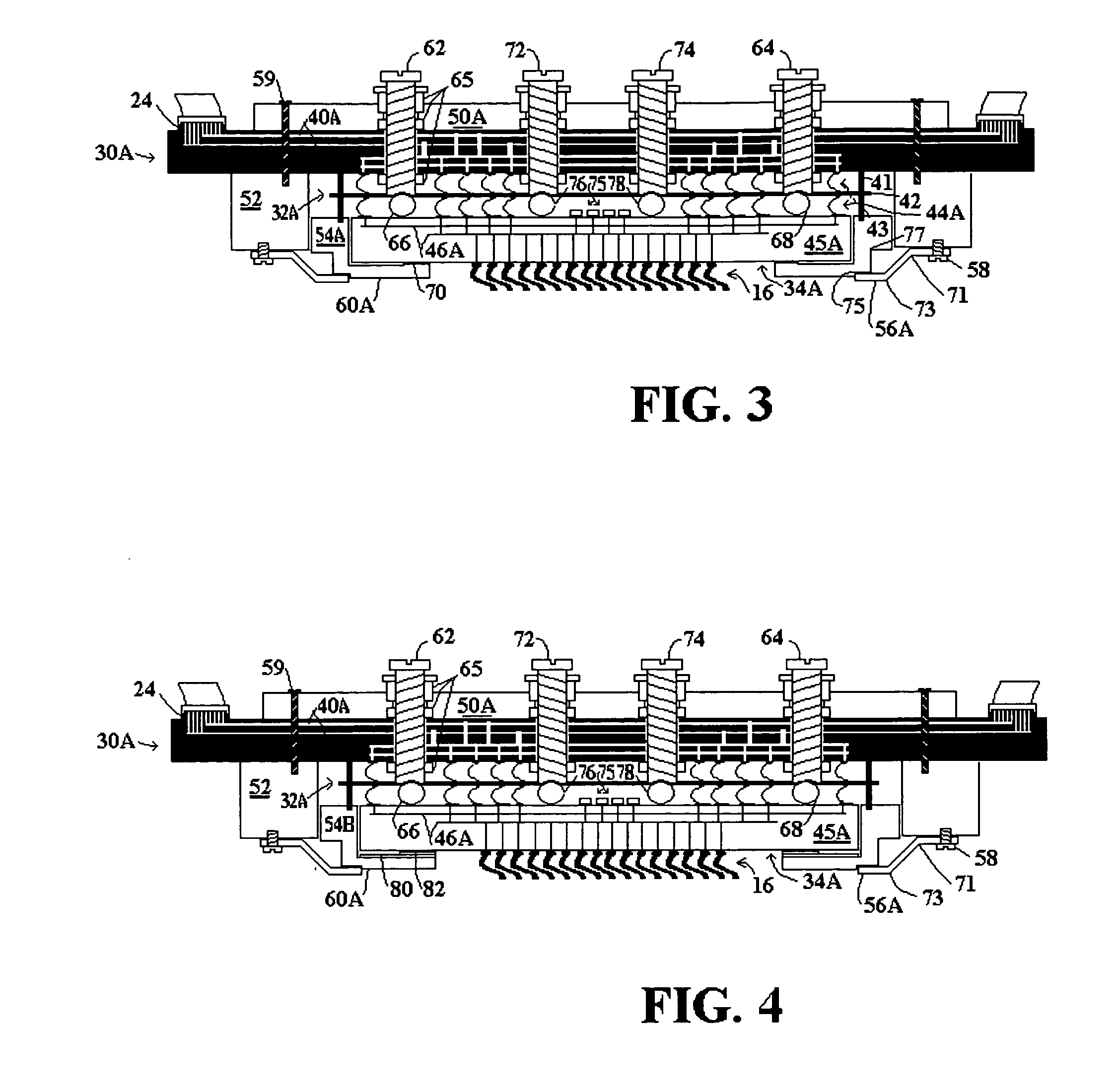
[0043]FIG. 3 is a cross sectional view of a probe card for a wafer test system with modifications made in accordance with the present invention to provide additional mechanical support for low flexural stiffness / strength substrates. The probe card of FIG. 3 includes components providing electrical pathways, similar to the conventional probe card of FIG. 2, including a printed circuit board (PCB) 30A, an interposer 32A, and a space transformer 34A. The probe card of FIG. 3 further includes mechanical support for the electrical components, similar to the conventional probe card of FIG. 2, including a drive plate 50A, frame (Probe Head Frame) 54A, bracket (Probe Head Bracket) 52, and leaf springs 56A. Components carried over from FIG. 2 are similarly numbered in FIG. 3, with modified components including the letter “A” after the reference number.

[0044] Modifications to the probe card of the present invention contemplate space transformer substrates possessing limited flexural strength...


PUM


Abstract

A mechanical support configuration for a probe card of a wafer test system is provided to increase support for a very low flexural strength substrate that supports spring probes. Increased mechanical support is provided by: (1) a frame around the periphery of the substrate having an increased sized horizontal extension over the surface of the substrate; (2) leaf springs with a bend enabling the leaf springs to extend vertically and engage the inner frame closer to the spring probes; (3) an insulating flexible membrane, or load support member machined into the inner frame, to engage the low flexural strength substrate farther away from its edge; (4) a support structure, such as support pins, added to provide support to counteract probe loading near the center of the space transformer substrate; and / or (5) a highly rigid interface tile provided between the probes and a lower flexural strength space transformer substrate.

Description

PRIORITY CLAIM TO PROVISIONAL APPLICATION [0001] This Patent Application claims priority to U.S. Provisional Patent Application No. 60 / 537,324, entitled “Probe Card Configuration For Low Mechanical Flexural Strength Electrical Routing Substrates,” filed Jan. 16, 2004.BACKGROUND [0002] 1. Technical Field [0003] The present invention relates in general to a configuration of a test system for testing integrated circuits on a wafer. More particularly, the present invention relates to a probe card mechanical support configuration for probe cards with low mechanical flexural strength electrical routing substrates. [0004] 2. Related Art [0005] With an increased size of wafers, a corresponding increase in size and complexity of test system probe cards for testing the wafers occurs. With the larger wafers, probe card substrates in the wafer test system are typically larger and designed to support more probes, or spring contacts, to connect to and test more integrated circuits (ICs) on the wa...

Claims


Application Information

Patent Timeline
Patent Type & Authority Applications(United States)
IPC IPC(8): G01R31/02G01R31/28
CPCG01R31/2889G01R1/07378H01L22/00
Inventor SHINDE, MAKARAND S.LARDER, RICHARD A.COOPER, TIMOTHY E.SHENOY, RAVINDRA V.ELDRIDGE, BENJAMIN N.
Owner FORMFACTOR INC
Learn More