Backlight unit and liquid crystal display having the same

a backlight unit and liquid crystal display technology, applied in gearing details, lighting and heating apparatus, instruments, etc., can solve the problems of high brightness and general insufficient brightness, and achieve the effect of efficient disposal

Active Publication Date: 2006-11-02
SAMSUNG DISPLAY CO LTD
View PDF8 Cites 36 Cited by
  • Summary
  • Abstract
  • Description
  • Claims
  • Application Information

AI Technical Summary

Benefits of technology

[0011] Accordingly, it is an aspect of the present invention to provide a backlight unit on which a point light source is efficiently disposed.
[0012] Accordingly, it is another aspect of the present invention to provide an LCD on which a point light source is efficiently disposed.
[0013] Accordingly, it is another aspect of the present invention to provide an efficient arrangement method of a point light source according to an LCD.

Problems solved by technology

The direct type backlight unit provides a high level of brightness by using a plurality of light sources, as compared with the edge type backlight unit, but the brightness is generally not sufficiently uniform.
However, in LCDs utilizing the above-described arrangement, the brightness is high directly above the LED circuit board, but is not as high in the regions between adjacent LED circuit boards.

Method used


Image

  • Backlight unit and liquid crystal display having the same
  • Backlight unit and liquid crystal display having the same
  • Backlight unit and liquid crystal display having the same

Examples


first embodiment

[0066] the present invention will be described with reference to the FIGS. 1 through 3.

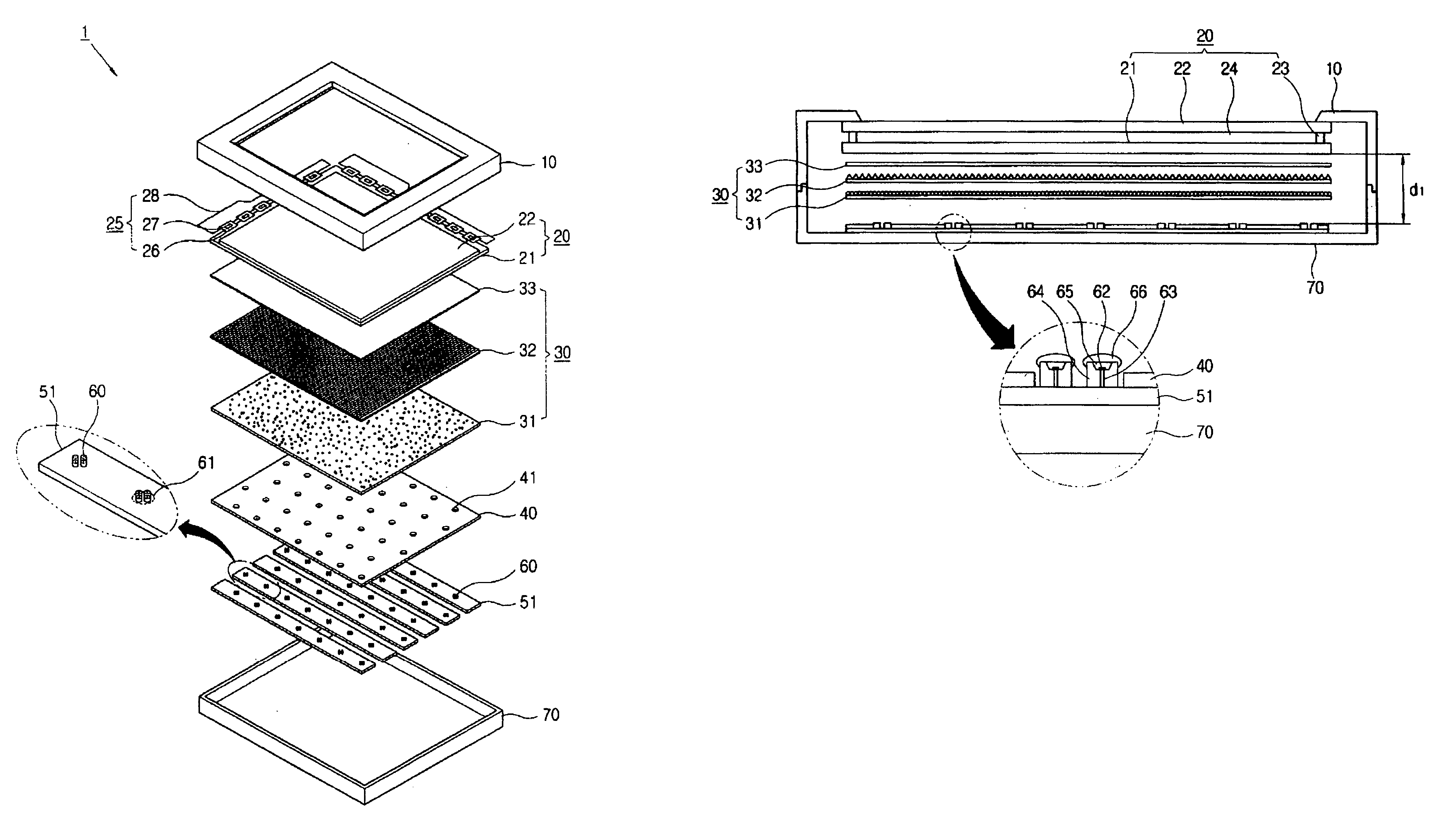
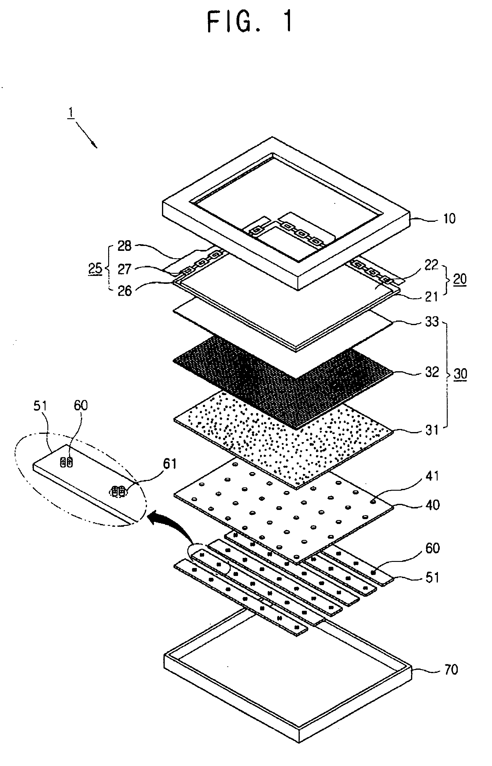
[0067] An LCD 1 comprises an LCD panel 20, a light regulating part 30, a reflecting plate 40, and an LED circuit board 51, which are disposed sequentially in the rear of the LCD panel 20. The LCD 1 further comprises one or more LED devices 60 seated on the LED circuit board 51 and disposed corresponding to an LED aperture 41 of the reflecting plate 40.

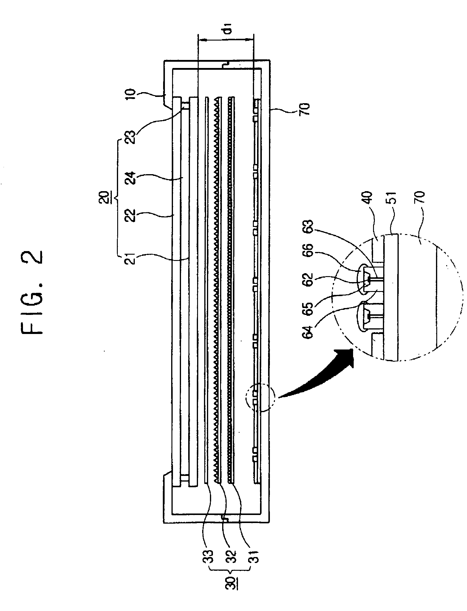
[0068] The LCD panel 20, the light regulating part 30, and the LED circuit board 51 are accommodated between an upper chassis 10 and a lower chassis 70.

[0069] The LCD panel 20 comprises a TFT substrate 21 on which TFTs are formed, a color filter substrate 22 facing the TFT substrate 21, a sealant 23 adhering the two substrates 21 and 22 and forming a cell gap, and a liquid crystal layer 24 encompassed by the two substrates 21 and 22 and the sealant 23. The LCD panel according to the first embodiment is formed in a rectangular shape having a long si...

second embodiment

[0101] the LED devices 60 are not provided in a regular arrangement. In other words, not all of the white light providing units 61 are provided in the center of the cells. The white light providing units 61 in the inside cells 81 closest to the short side are disposed at a position closer to the short side. This arrangement supplements the brightness of the second short side cells 82 which do not include white light providing units 61.

[0102] The distance between the LED devices 60 and an LCD panel 20 should be increased to provide good color mixing of the LED device 60. In contrast, the distance between the LED device 60 and the LCD panel 20 should be reduced in order to provide the LCD 1 with a thin profile. Due to the desire to obtain a thin LCD 1, adjusting the effective length by increasing the distance between the LED device 60 and the LCD panel 20 can be difficult. In addition, the size of the LCD panel 20 is also not easily adjusted. Accordingly, the optimal relationship bet...

third embodiment

[0103] A third embodiment will be described with reference to FIG. 10.

[0104]FIG. 10 shows an arrangement of an LED 60 according to the third embodiment. A pair of opposing sides in an inside cell 81 are disposed parallel with a short side of an arrangement surface. A short side cell 82 is bisected by a short side, thereby making its surface area approximately 50% of an area of the inside cell 81. A white light providing unit is provided in the short side cell 82 at a position closer to the side of the short side cell 82 than in the inside cell 81. A long side cell 83 is also bisected by a long side, thereby making its surface area approximately 50% of the surface area of the inside cell 81. A white light providing unit is also provided in the long side cell 83 at a position closer to the top of the long side cell 83 than in the inside cell 81. A corner cell 84 is intersected by both the long side and the short side, thereby making its surface area approximately 25% of the surface ar...


PUM

PropertyMeasurementUnit
length L6aaaaaaaaaa
length L6aaaaaaaaaa
length L6aaaaaaaaaa

Abstract

A backlight unit comprises an arrangement surface and a plurality of point light sources arranged on the arrangement surface, wherein the arrangement surface is divided into an array of hexagonal cells, a plurality of the cells comprising a white light providing unit. An LCD comprising a backlight unit on which a point light source is efficiently disposed and an efficient arrangement method of a point light source are provided.

Description

CROSS-REFERENCE TO RELATED APPLICATIONS [0001] This application claims the benefit of Korean Patent Application No. 2005-0036094, filed on Apr. 29, 2005, in the Korean Intellectual Property Office, the disclosure of which is incorporated herein by reference. BACKGROUND [0002] 1. Field of the Invention [0003] The present invention relates to a backlight unit and a liquid crystal display having the same, and more particularly, to a backlight unit and a liquid crystal display having the same on which a point light source is efficiently disposed. [0004] 2. Description of the Related Art [0005] Recently, flat panel display apparatuses, such as LCD (liquid crystal display), PDP (plasma display panel), and OLED (organic light emitting diode) display types, has been developed in place of a CRT (cathode ray tube) display type. [0006] A typical liquid crystal display (hereinafter referred to as ‘LCD’) comprises an LCD panel having a TFT substrate, a color filter substrate, and a liquid crysta...

Claims


Application Information

Patent Timeline
Patent Type & Authority Applications(United States)
IPC IPC(8): G02F1/1335F21S2/00F21Y101/02G02F1/13357
CPCG02F2001/133613G02F1/133603G02F1/133613F16H57/029F16H57/0472F16H2057/02047
Inventor YOON, JU-YOUNGKIM, GI-CHERLKIM, HYUN-JINLEE, SANG-YU
Owner SAMSUNG DISPLAY CO LTD
Why Eureka
Try Eureka