Projection optical system

a technology of projection optical system and projection optical element, which is applied in the field of projection optical element, can solve the problems of deteriorating the sharpness level (resolution feeling) of an image, deteriorating image quality, and affecting the quality of images, so as to achieve higher resolution and higher grade

Active Publication Date: 2006-11-02
KONICA MINOLTA OPTO
View PDF8 Cites 30 Cited by
  • Summary
  • Abstract
  • Description
  • Claims
  • Application Information

AI Technical Summary

Benefits of technology

[0014] In view of such a condition, the present invention has been made, and it is an object of the invention to provide a p

Problems solved by technology

The refractive optical system typically has lateral chromatic aberration which deteriorates the sharpness level (resolution feeling) of an image.
The intensity distribution is mountain-shaped due to the oblique pixel arrangement; as a result, a deep valley is formed between the peak of G and the peak of R and B, thus resulting in a double-line-like appearance of the projected image, which leads to deterioration in image quality (resolution feeling in particular).
In addition, the same problem of a double line also appears in the case of pixel arrangement with square arrays having a small aperture ratio.
Even when a double line is not formed, lateral chromatic aberration damages the resolution feeling of an image, thus reducing the effect of pixel shift.

Method used


Image

  • Projection optical system
  • Projection optical system
  • Projection optical system

Examples


example

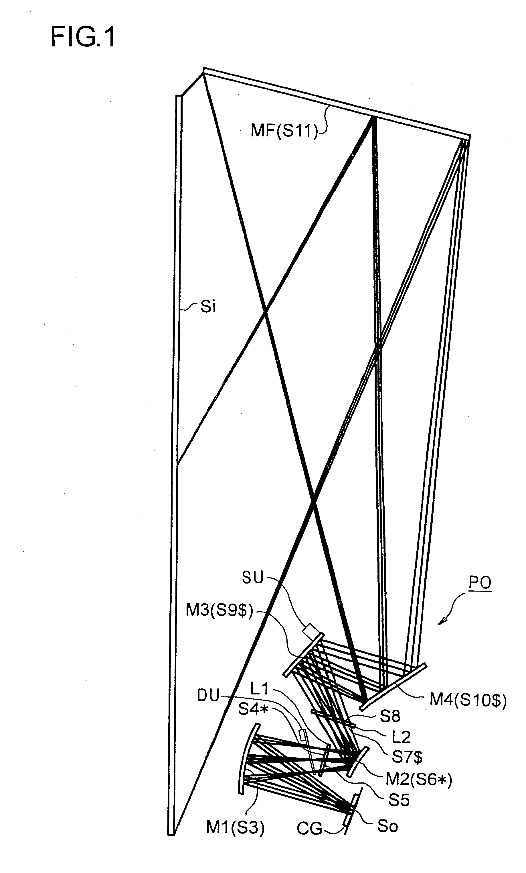
[0074] Hereinafter, a practical example of the projection optical system, the image projection apparatus, and the like embodying the present invention will be presented with reference to their construction data and the like. The example presented below is a numerical example of a projection optical system corresponding to the embodiment described previously. Thus, the optical construction diagram of the projection optical system shown in FIG. 1 shows the optical arrangement, projection optical path, and other features of the example. The construction data of the example shows the optical arrangement of the system including from the display device surface So at the reduction side (corresponding to the object surface in enlargement projection) to the screen surface Si at the enlargement side (corresponding to the image surface in enlargement projection). The n-th surface counted from the reduction side is represented by Sn (n=1, 2, 3, . . . ). It should be noted that surfaces S1 and S...


PUM


Abstract

A projection optical system that performs enlargement projection of an image on a display device surface formed of a plurality of pixels onto a screen surface, in which pixel shift by less than a pixel pitch is performed on the screen surface in a vertical direction, a horizontal direction, an oblique direction, or a vertical and horizontal directions, and in which conditional formulae (1) and (2) below are fulfilled over the entire image range: (1)|ΔΔRG|≦0.5 d and (2)|ΔBG|≦0.5 d, where d represents the amount of pixel shift (>0), ΔRG represents lateral chromatic aberration in the direction of pixel shift of colored light R having a wavelength of 640 nm with respect to colored light G having a wavelength of 546 nm, and ΔBG represents lateral chromatic aberration in the direction of pixel shift of colored light B having a wavelength of 450 nm with respect to the colored light G having a wavelength of 546 nm.

Description

[0001] This application is based on Japanese Patent Application No. 2005-130772 filed on Apr. 28, 2005, the contents of which are hereby incorporated by reference. BACKGROUND OF THE INVENTION [0002] 1. Field of the Invention [0003] The present invention relates to a projection optical system, and more specifically to an image projection apparatus having, for example, a digital micromirror device or a LCD (liquid crystal display), as a display device and to a projection optical system that is mounted in the image projection apparatus and that perform enlargement projection of an image formed on the surface of the display device onto the screen surface. [0004] 2. Description of Related Arts [0005] As an image display for use in digital satellite broadcasts at home and a home theater, low-cost and high-performance image projection apparatuses (that is, projectors) having a digital micromirror device or an LCD as a display device have been becoming increasingly widespread in recent year...

Claims


Application Information

Patent Timeline
IPC IPC(8): G03B21/14
CPCG02B17/0663G03B21/10H04N5/7416G03B21/28G03B21/14G03B21/2053H04N9/3141G03B21/006
Inventor HAYASHI, KOHTAROIMAOKA, MASAYUKIATARASHI, YUICHIKIBAYASHI, HIROSHI
Owner KONICA MINOLTA OPTO
Why Eureka
Try Eureka