Secondary battery module having piezo sensor

a secondary battery and piezo sensor technology, applied in the direction of secondary battery servicing/maintenance, cell components, electrochemical generators, etc., can solve the problems of weak lithium secondary battery, deformation of the case, and swelling of the electrode assembly or the battery case, so as to achieve accurate measurement, widen the channel, and increase the thickness of the unit cell.

Active Publication Date: 2006-11-02
LG ENERGY SOLUTION LTD
View PDF6 Cites 78 Cited by
  • Summary
  • Abstract
  • Description
  • Claims
  • Application Information

AI Technical Summary

Benefits of technology

[0025] The present invention is characterized in that, when the width of the channel defined between the unit cells is decreased due to the volume expansion of the unit cells caused by the increase of the internal pressure of the unit cells, such change is accurately measured to control the operation of the battery module.
[0026] The experiments performed by the inventors revealed that the increase of the internal pressure of the unit cells is gr

Problems solved by technology

Although the lithium secondary battery has many advantages as compared to the conventional nickel-cadmium battery or the conventional nickel-metal hydride battery, the lithium secondary battery has a problem in that the lithium secondary battery is weak.
In this case, however, when the battery is overcharged or when the battery is left at high temperature, the electrode assembly or the battery case may swell due to the increase of the internal pressure of the battery.
As a result, the case may be deformed.
This deformation of the case may cause the explosion of the battery.
However, satisfactory stability is not guaranteed by these conventional methods.
However, the above-described system for measuring the swelling of the battery case does not provide high reliability.
Also, it is difficult to stably mount the sensor to the surface of the pouch-shaped battery for the purpose

Method used


Image

  • Secondary battery module having piezo sensor
  • Secondary battery module having piezo sensor
  • Secondary battery module having piezo sensor

Examples


Embodiment Construction

[0042] Now, a preferred embodiment of the present invention will be described in detail with reference to the accompanying drawings. It should be noted, however, that the scope of the present invention is not limited by the illustrated embodiment.

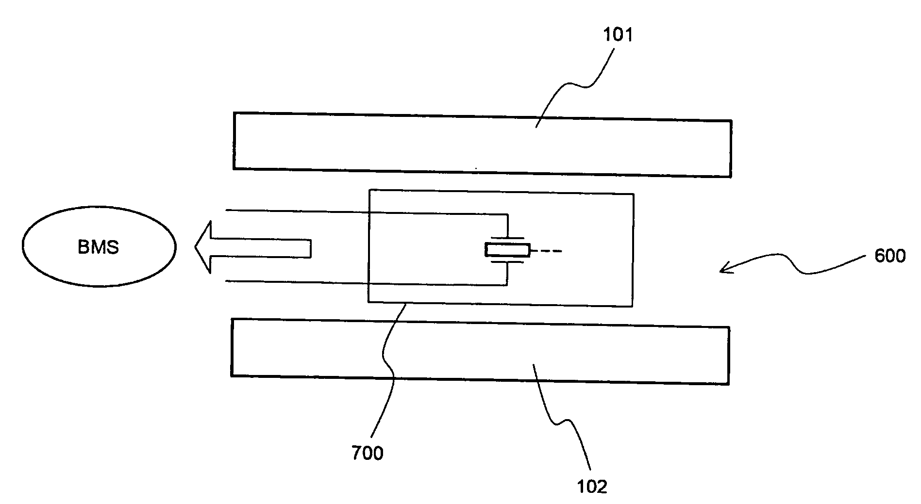
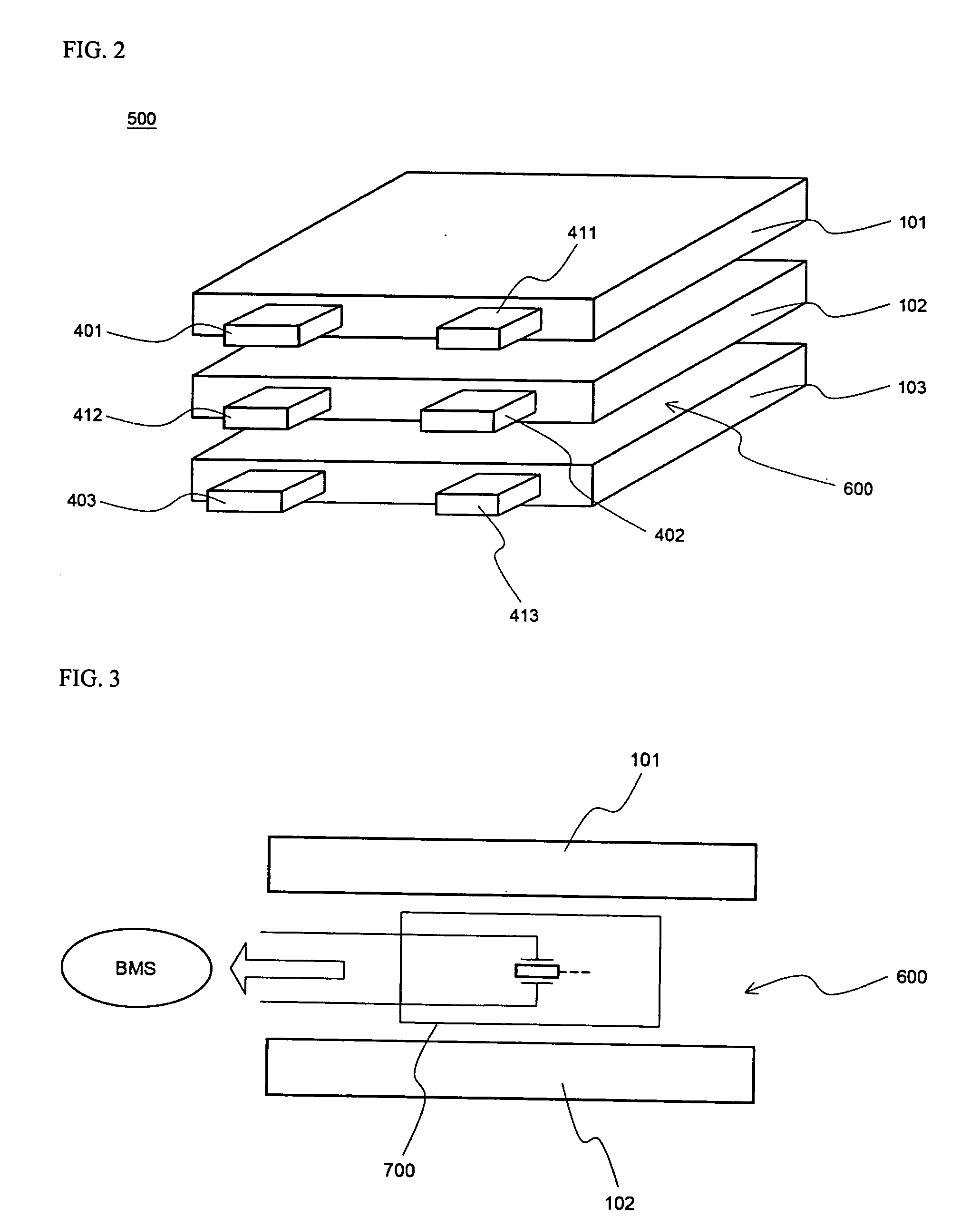
[0043]FIG. 3 is a typical view illustrating the structure of a secondary battery module having a piezoelectric sensor according to a preferred embodiment of the present invention.

[0044] Referring to FIG. 3, the secondary battery module includes unit cells 101 and 102, which are stacked one on another while being spaced a predetermined distance from each other such that a channel 600, in which heat generated during the charge and discharge of the battery is removed, is defined between unit cells 101 and 102. In the channel 600 is mounted a piezoelectric sensor 700, which detects the increase of the internal pressure of the unit cells 101 and 102 located at opposite sides of the piezoelectric sensor 700. Consequently, no additional space fo...


PUM


Abstract

Disclosed herein is a secondary battery module comprising a plurality of unit cells stacked one on another, wherein the unit cells are spaced apart from each other such that a channel for heat dissipation is defined between the unit cells, the battery module further comprises at least one piezoelectric sensor mounted in the channel, and the at least one piezoelectric sensor is connected to a battery management system (BMS). According to the present invention, the piezoelectric sensor is mounted in the channel defined between the unit cells of the secondary battery module. Consequently, no additional space for installing the piezoelectric sensor is needed, and therefore, the increase of the size of the battery module is effectively prevented. Furthermore, the change of the internal pressure of the battery is accurately detected by the piezoelectric sensor, and therefore, the expansion or the explosion of the battery caused due to the overcharge or overheating of the unit cells is effectively prevented.

Description

FIELD OF THE INVENTION [0001] The present invention relates to a secondary battery module, and, more particularly, to a secondary battery module wherein a piezoelectric sensor is mounted in a channel defined between unit cells when the unit cells are arranged to assemble the secondary battery module, such that, when the internal pressure of the unit cells is increased due to the abnormal operation of the unit cells, pressure caused by the expansion of the unit cells is applied to the piezoelectric sensor, voltage is generated at the output terminal of the piezoelectric sensor, and the generated sensor voltage is transmitted to a control unit, such as a battery management system (BMS), at which a control algorithm is performed, whereby the expansion or the explosion of the battery caused due to the overcharge or overheating of the unit cells is effectively prevented, and therefore, the stability of battery is improved. BACKGROUND OF THE INVENTION [0002] As mobile devices have been in...

Claims


Application Information

Patent Timeline
IPC IPC(8): H01M10/50
CPCH01M10/4207H01M10/482H01M10/425Y02E60/10H01M50/20H01M50/572
Inventor YOON, YEO WONJUNG, DO YANG
Owner LG ENERGY SOLUTION LTD
Why Eureka
Try Eureka