
Elevated height electrical connector

a technology of electrical connectors and heights, applied in the direction of securing/insulating coupling contact members, fixed connections, coupling device connections, etc., can solve the problems of increased manufacturing steps, increased height of electrical connectors, and lower performance of elevated height electrical connectors compared to lower height electrical connectors. , to achieve the effect of increasing height, convenient assembly and reliabl

Active Publication Date: 2006-11-02
SAMTEC
View PDF25 Cites 10 Cited by
  • Summary
  • Abstract
  • Description
  • Claims
  • Application Information

AI Technical Summary

Benefits of technology

[0020] To overcome the problems described above, preferred embodiments of the present invention provide an electrical connector having an increased height that is easy to assemble and reliably and safely position contacts in the electrical connector.

Problems solved by technology

Thus, elevated height electrical connectors have lower performance compared to lower height electrical connectors.
Further, elevated height electrical connectors typically require several extra manufacturing steps not required for lower height electrical connector.
These extra manufacturing steps add additional material and labor cost.

Method used


Image

  • Elevated height electrical connector
  • Elevated height electrical connector
  • Elevated height electrical connector

Examples


Embodiment Construction

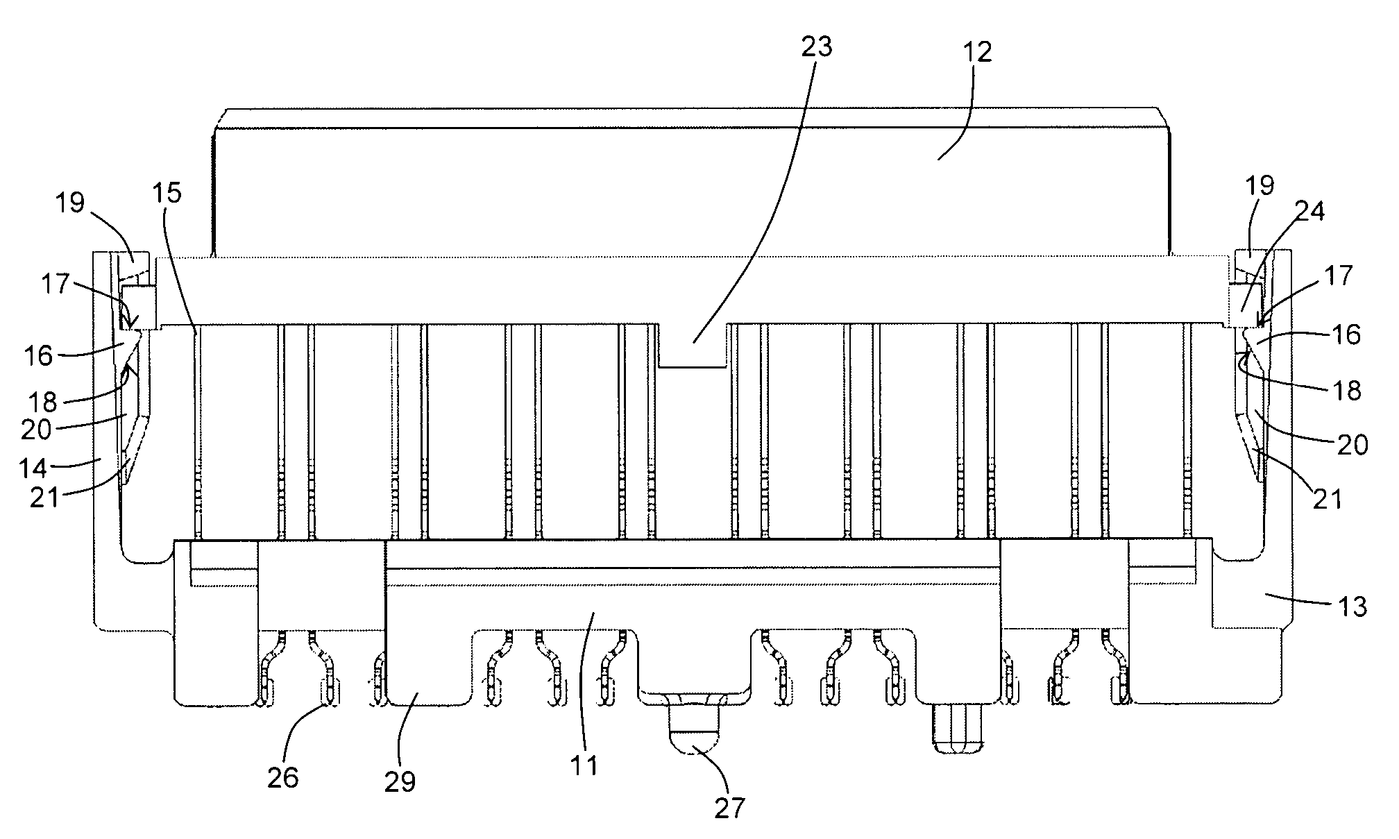
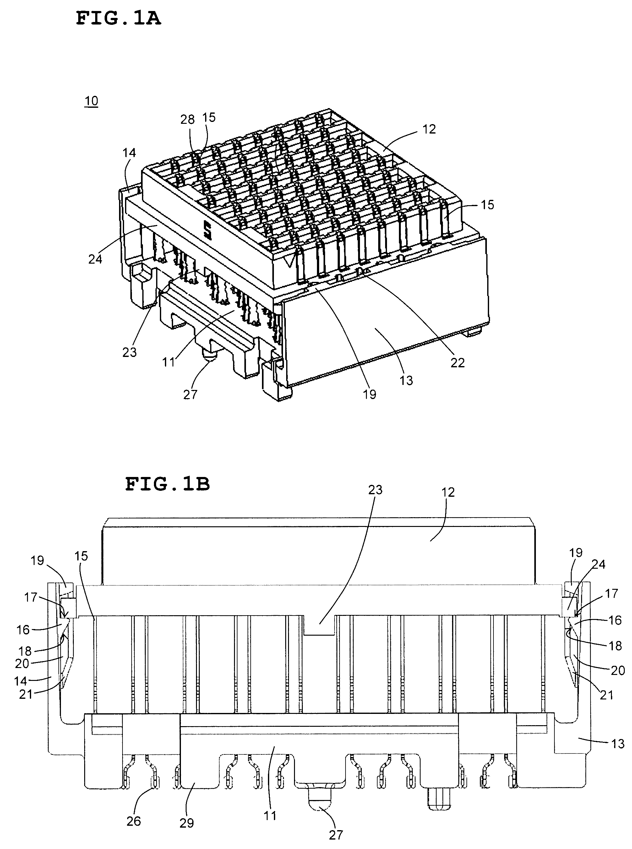
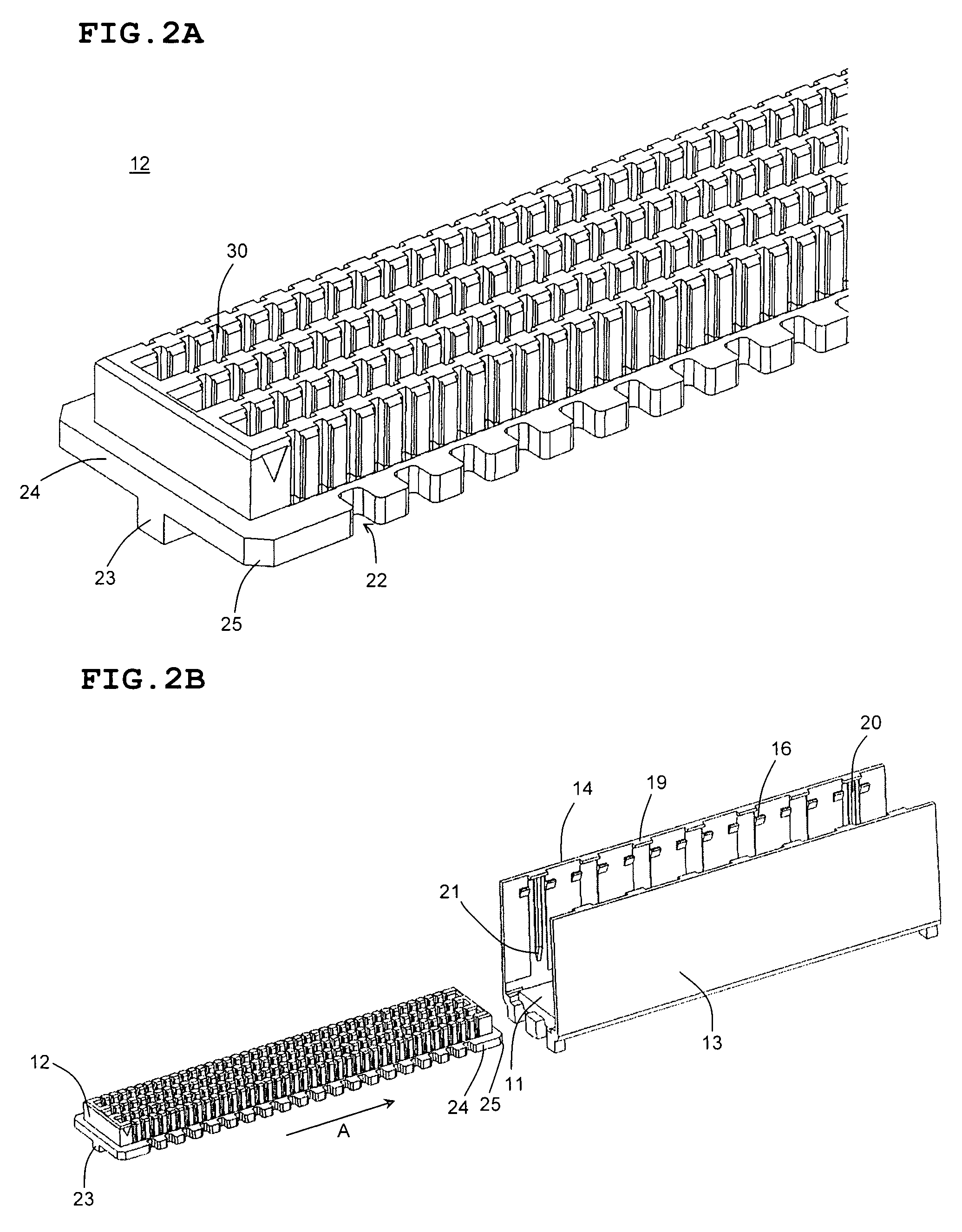
[0060]FIGS. 1A and 1B illustrate an electrical connector 10 according to the preferred embodiment of the present invention. Electrical connector 10 includes a first connector body 11 and a second connector body 12. The first connector body 11 and the second connector body 12 locate and support a plurality of electrical contacts 15.

[0061] The cores 30 of the first connector body 11 and the second connector body 12 can be arranged in any suitable manner depending upon the type or types of electrical signals that will be transmitted through the electrical connector 10. FIGS. 5A-5F are schematic drawings illustrating various possible core arrangements. However, electrical connector 10 could have any core arrangement.

[0062]FIG. 5A illustrates a core arrangement in which the cores 30 are arranged in a regular array. That is, each core 30a is spaced the same distance from the cores 32a nearest to it. The core arrangement shown in FIG. 5A could be used to transmit both single-ended and di...


PUM

PropertyMeasurementUnit
lengthaaaaaaaaaa
distanceaaaaaaaaaa
acute angleaaaaaaaaaa

Abstract

An electrical connector includes first and second connector bodies which are arranged to first be positioned together, and then separated once electrical contacts have been inserted in at least one of the first and second connector bodies. During, after, or both during and after the separating of the two connector bodies, portions of the first and second connector bodies are in direct contact with each other. The first connector body has first and second walls extending therefrom. At least one ramp and at least one stop are arranged on at least one of the first wall, the second wall, and the second connector body. At least one protrusion is arranged on at least one of the first wall, the second wall, and the second connector body. The at least one ramp, the at least one stop, and the at least one protrusion are arranged such that, when the at least one ramp and the at least one stop engage the at least one protrusion, a distance between the first and second connector bodies is fixed.

Description

BACKGROUND OF THE INVENTION [0001] 1. Field of the Invention [0002] The present invention relates to electrical connectors. More specifically, the present invention relates to elevated height electrical connectors. [0003] 2. Description of the Related Art [0004] As an electrical connector becomes taller, signal integrity performance of the electrical connector decreases. Thus, elevated height electrical connectors have lower performance compared to lower height electrical connectors. Further, elevated height electrical connectors typically require several extra manufacturing steps not required for lower height electrical connector. These extra manufacturing steps add additional material and labor cost. [0005] In known elevated height electrical connectors, electrical contacts are supported on each end by one of a first and a second connector body. Extra support mechanisms are typically disposed between the first and second connector bodies, which require secondary manufacturing step...

Claims


Application Information

Patent Timeline
Patent Type & Authority Applications(United States)
IPC IPC(8): H01R13/514
CPCH01R12/57H01R13/405H01R13/41H01R13/506H01R13/514H01R43/20Y10T29/49147H01R12/7052Y10T29/49218Y10T29/49117Y10T29/49208Y10T29/49204H01R13/6471
Inventor MONGOLD, JOHN A.
Owner SAMTEC
Learn More