Electronic differential lock assembly

a technology of differential lock and electronic components, applied in the direction of differential gearings, belts/chains/gearrings, mechanical instruments, etc., can solve the problems of increasing assembly time, increasing assembly time, and driving up the overall system cost, so as to reduce the number of components and reduce assembly time , the effect of simplifying and effective differential lock

Active Publication Date: 2006-11-02
MERITOR HEAVY VEHICLE SYST CAMERI
View PDF6 Cites 17 Cited by
  • Summary
  • Abstract
  • Description
  • Claims
  • Application Information

AI Technical Summary

Benefits of technology

[0014] The subject invention provides a simplified and effective differential lock that significantly reduces the number of components from traditional designs, reduces assembly time,

Problems solved by technology

Some disadvantages with the air actuation method are the significant number of components that are required, leakage, and component wear.
The significant number of components that are required to operate this system increase assembly time and drive up the overall system cost.
Requiring an air connect to actuate the system introduces possible air leaks to the system, which can lead to inadequate system performance.
Further, the differential ge

Method used


Image

  • Electronic differential lock assembly
  • Electronic differential lock assembly
  • Electronic differential lock assembly

Examples


Embodiment Construction

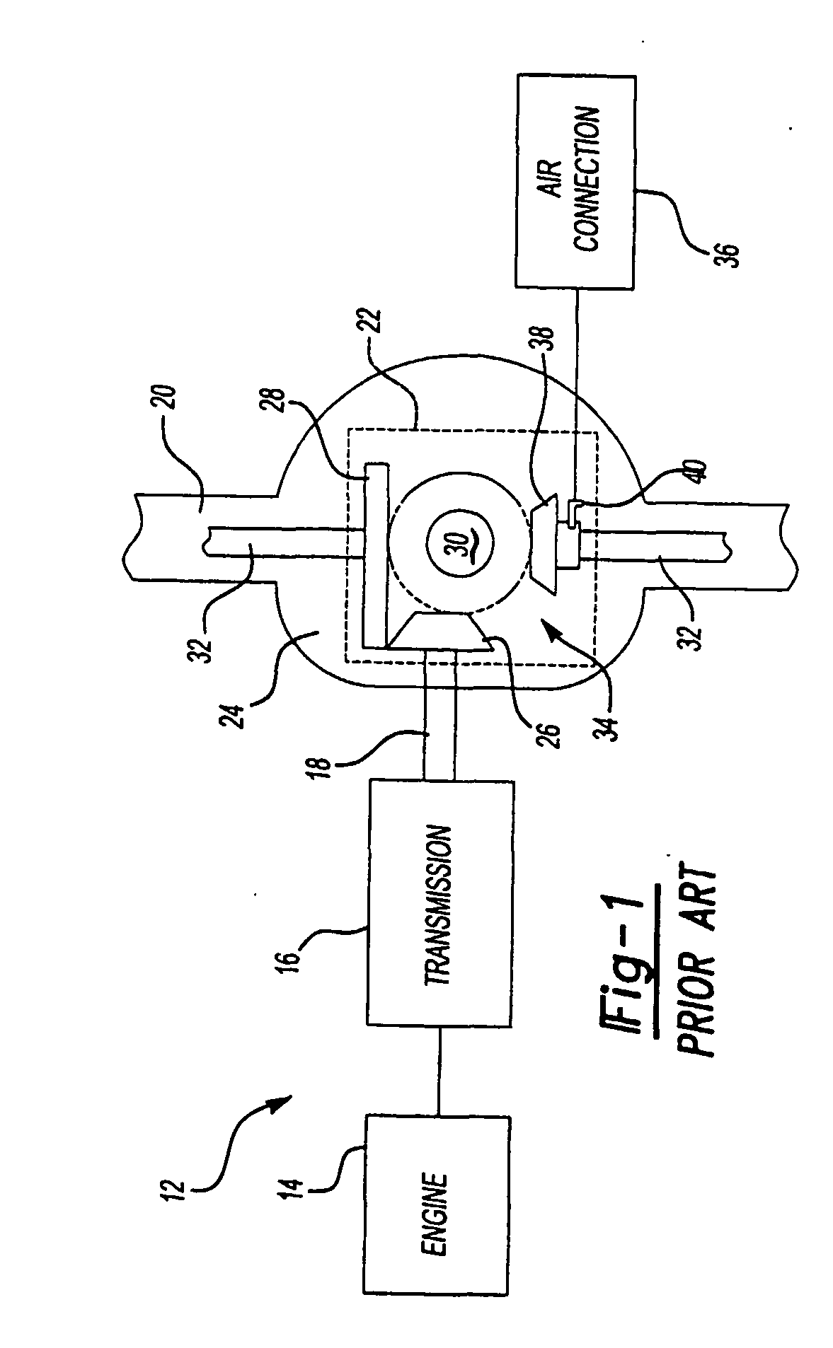
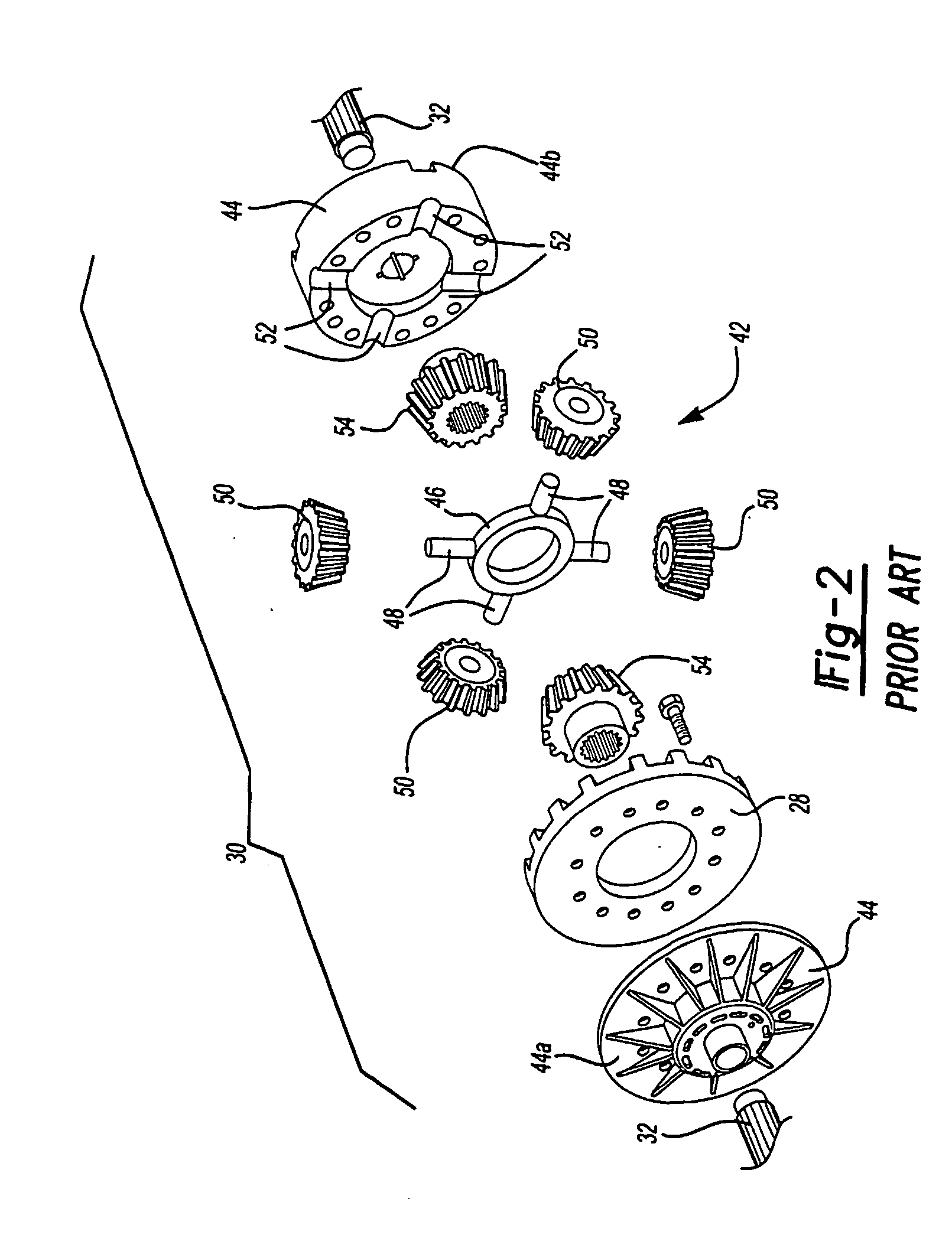
[0025] A traditional powertrain with an air-actuated differential locking mechanism is shown generally at 12 in FIG. 1. The powertrain 12 includes an engine 14, transmission 16, and drive shaft 18 that is coupled to a drive axle 20. The drive axle 20 includes a carrier 22 positioned within an axle housing 24 as known. The carrier 22 includes a pinion gear 26, operably coupled to the drive shaft 18, and which is in driving engagement with a ring gear 28. The ring gear 28 drives a differential 30, which in turn drives a pair of axle shafts 32 that drive the vehicle wheels (not shown).

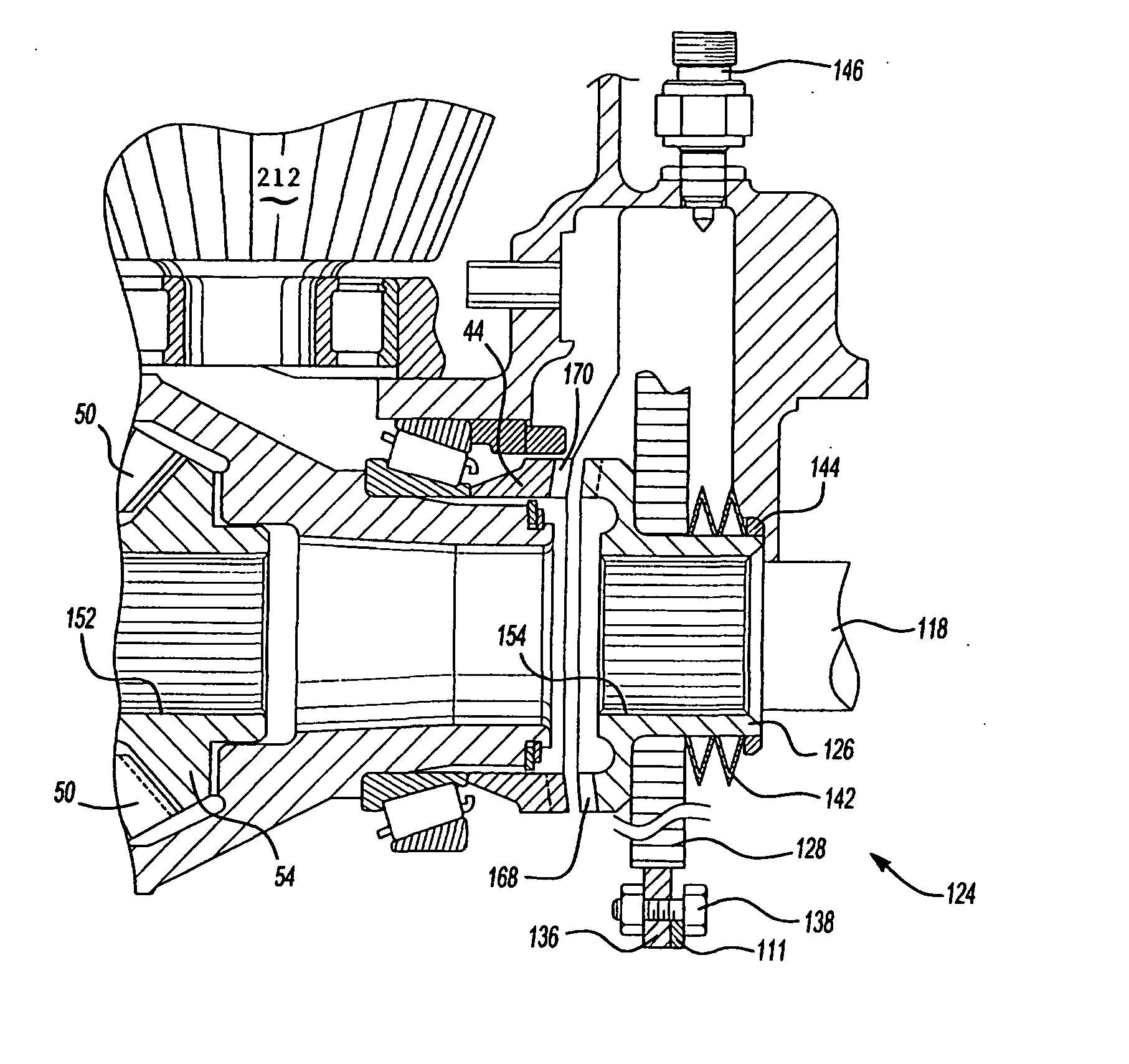
[0026] The differential 30 includes a differential locking mechanism, shown generally at 34, which is actuated via an air supply connection 36. The differential locking mechanism 34 is movable between an unlocked position where axle shaft speed differentiation is permitted and a locked position where the axle shafts are locked together to rotate at a common speed. The differential locking mechanism 34 in...


PUM


Abstract

An electronic differential lock assembly includes a shift collar that is movable in response to an electronic signal from an unlocked position where axle shaft speed differentiation under predetermined conditions is permitted to a locked position where a pair of axle shafts are fixed for rotation together. Speed differentiation is provided by a differential that includes a differential gear assembly supported within a differential case. A coil surrounds the shift collar and is selectively energized to move the shift collar from the unlocked position to the locked position. The shift collar is splined to one of the axle shafts and is selectively splined to the differential case to lock the axle shafts together. The electronic differential lock assembly includes a return spring that automatically disengages the shift collar from the differential case once the coil is no longer energized.

Description

BACKGROUND OF THE INVENTION [0001] This invention relates to a differential locking assembly that utilizes an electronic coil to actuate a differential lock shift collar. [0002] Vehicle drive axles typically include a pair of axle shafts for driving vehicle wheels. The drive axle uses a differential to control input speed and torque to the axle shafts. Under ideal conditions, when the vehicle is driven along a straight path, the wheels will be turning at approximately the same speed and the torque will be equally split between both wheels. When the vehicle negotiates a turn, the outer wheel must travel over a greater distance than the inner wheel. The differential allows the inner wheel to turn at a slower speed than the outer wheel as the vehicle turns. [0003] Power is transmitted from a vehicle drive shaft to a pinion gear that is in constant mesh with a differential ring gear. The ring gear is bolted to a differential housing or case that turns with the ring gear. A differential ...

Claims


Application Information

Patent Timeline
IPC IPC(8): F16H48/06F16H48/30
CPCF16H48/08F16H48/24F16H48/30F16H2048/426F16H2048/204F16H2048/346F16H48/34
Inventor PONTANARI, MARCOBASSI, MARCOBELLOMI, GIOVANNIGIANONE, ROBERTO
Owner MERITOR HEAVY VEHICLE SYST CAMERI
Why Eureka
Try Eureka