Methods for securing spinal rods

a technology of spinal rods and screws, applied in the field of spinal rods secured, can solve the problems of damage to the fastener and the connective device with which it is associated, and limiting the range of motion of the spine, so as to facilitate the relative rotation of the two parts

Inactive Publication Date: 2006-11-02
HOWMEDICA OSTEONICS CORP
View PDF7 Cites 223 Cited by
  • Summary
  • Abstract
  • Description
  • Claims
  • Application Information

AI Technical Summary

Benefits of technology

[0015] Preferably, the locking cap is a two-piece structure which includes an upper portion configured to engage an interior surface of the head portion and a lower portion configured to engage an exterior surface of the spinal rod to secure the position of the head portion relative to the spinal rod upon rotation of the upper portion relative to the lower portion and the head portion. The upper portion of the locking cap includes a bottom surface having an axial reception bore defined therein and the lower portion of the locking cap includes an upper surface having an axial post extending therefrom configured to engage the axial reception bore in the bottom surface of the upper portion of the locking cap and facilitate the relative rotation of the two parts. The upper portion further includes opposed arcuate engagement flanges configured for cammed engagement in correspondingly configured opposed arcuate engagement slots formed in the opposed side walls of the head portion upon rotation of the upper portion relative to the lower portion. The lower portion further includes a bottom surface having an elongated hemi-cylindrical recess that is oriented to accommodate a spinal rod extending through the channel in the head portion.

Problems solved by technology

Trauma or developmental irregularities can result in spinal pathologies that limit this range of motion.
Furthermore, during assembly, excessive torque applied to a threaded fastener can cause damage to the fastener as well as to the connective device with which it is associated.

Method used


Image

  • Methods for securing spinal rods
  • Methods for securing spinal rods
  • Methods for securing spinal rods

Examples


Embodiment Construction

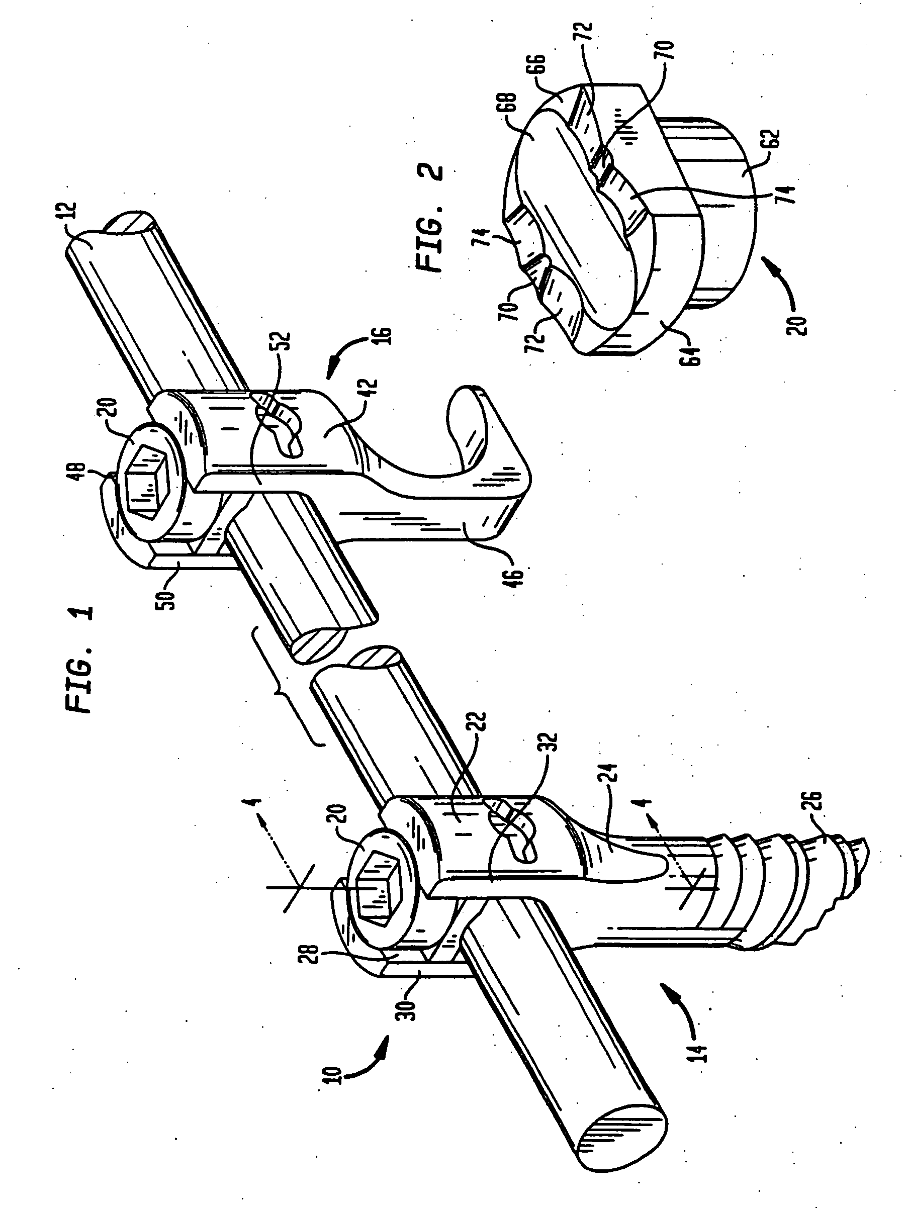
[0044] Referring now to the drawings wherein like reference numerals identify similar structural elements of the subject apparatus, there is illustrated in FIG. 1 a section of a spinal stabilization system constructed in accordance with a preferred embodiment of the subject disclosure and designated generally by reference numeral 10.

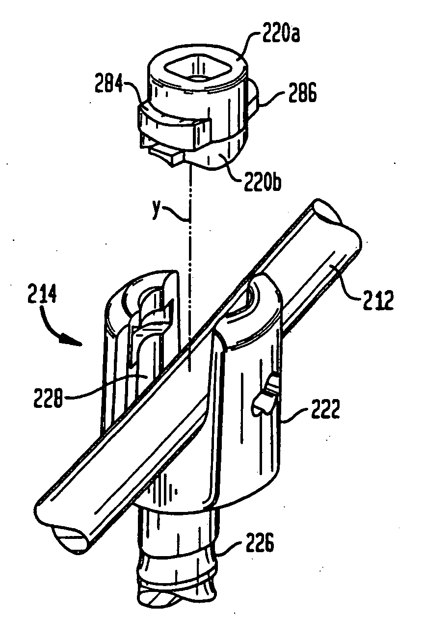
[0045] Referring to FIG. 1, spinal stabilization system 10 includes an elongated spinal rod 12 having a circular cross-section and a substantially smooth outer surface finish. As illustrated, fastening devices in the form of a bone screw 14 and right-angle hook 16 are provided for securing spinal rod 12 to the spine during a spinal stabilization procedure. Both fastening devices employ a novel top-loaded locking cap, designated generally by reference numeral 20, which will be described in greater detail hereinbelow with reference to FIG. 2. The novel locking cap achieves significant clinical advantages over the prior art through its reliability and the ...


PUM


Abstract

A method of securing a spinal rod to a spine includes providing a head portion having a channel extending therethrough for receiving a spinal rod, the channel and the head portion being bounded by a first side wall and a second side wall. The method includes providing a bone fastener depending from the head portion, arranging the spinal rod in the channel of the head portion, and providing a locking cap having first and second portions that are rotatable relative to one another, the second portion of the locking cap having an underside with a recess. The method includes assembling the locking cap with the head portion so that the first portion is between the first and second side walls and so that the recess of the second portion of the locking cap is in contact with the spinal rod. While maintaining the recess of the second portion of the locking cap in contact with the spinal rod, the first portion of the locking cap is rotated, such rotation translating into a locking force applied by the second portion of the locking cap onto the spinal rod.

Description

CROSS-REFERENCE TO RELATED APPLICATIONS [0001] The subject application is a continuation of U.S. application Ser. No. 10 / 365,182, filed Feb. 12, 2003, which is a continuation of U.S. application Ser. No. 09 / 487,942, filed Jan. 19, 2000, now U.S. Pat. No. 6,565,565, which is a continuation-in-part of both U.S. application Ser. No. 09 / 167,439, filed Oct. 6, 1998, now abandoned, and U.S. application Ser. No. 09 / 098,927, filed Jun. 17, 1998, now U.S. Pat. No. 6,090,111, the disclosures of which are hereby incorporated by reference herein.BACKGROUND OF THE INVENTION [0002] 1. Field of the Invention [0003] The subject disclosure relates to implantable spinal stabilization systems for surgical treatment of spinal disorders, and more particularly, to a device for connecting cylindrical spinal rods of a spinal stabilization system to the spine. [0004] 2. Background of the Related Art [0005] The spinal column is a complex system of bones and connective tissue that protects critical elements o...

Claims


Application Information

Patent Timeline
Patent Type & Authority Applications(United States)
IPC IPC(8): A61F2/30A61B17/58A61B17/00A61B17/56A61B17/70
CPCA61B17/7032A61B2017/00858A61B17/7037
Inventor YUAN, HANSENNICHOLS, DAVIDFINLEY, ERIC
Owner HOWMEDICA OSTEONICS CORP
Why Eureka
Try Eureka