Vacuum accessory tool
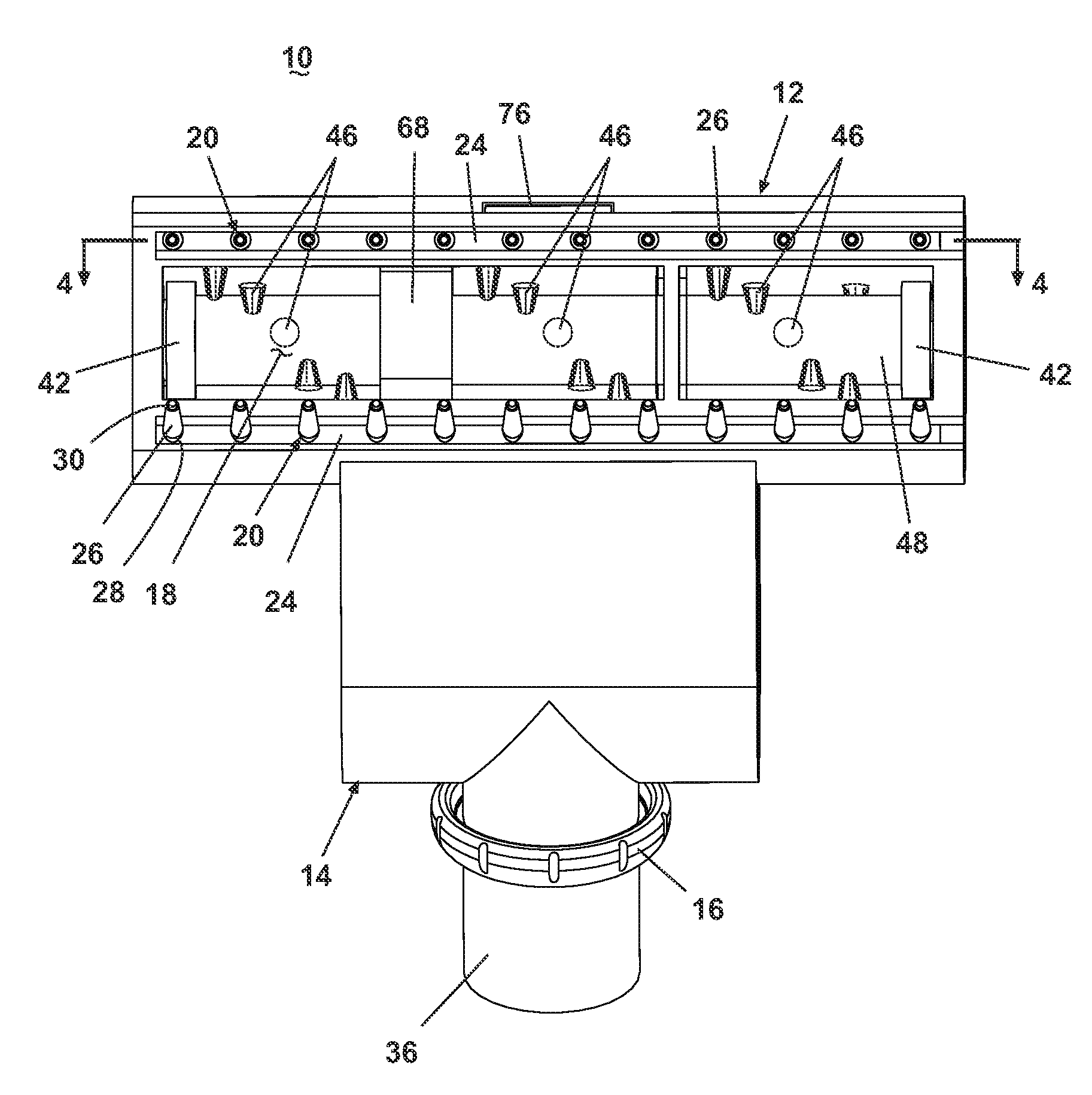
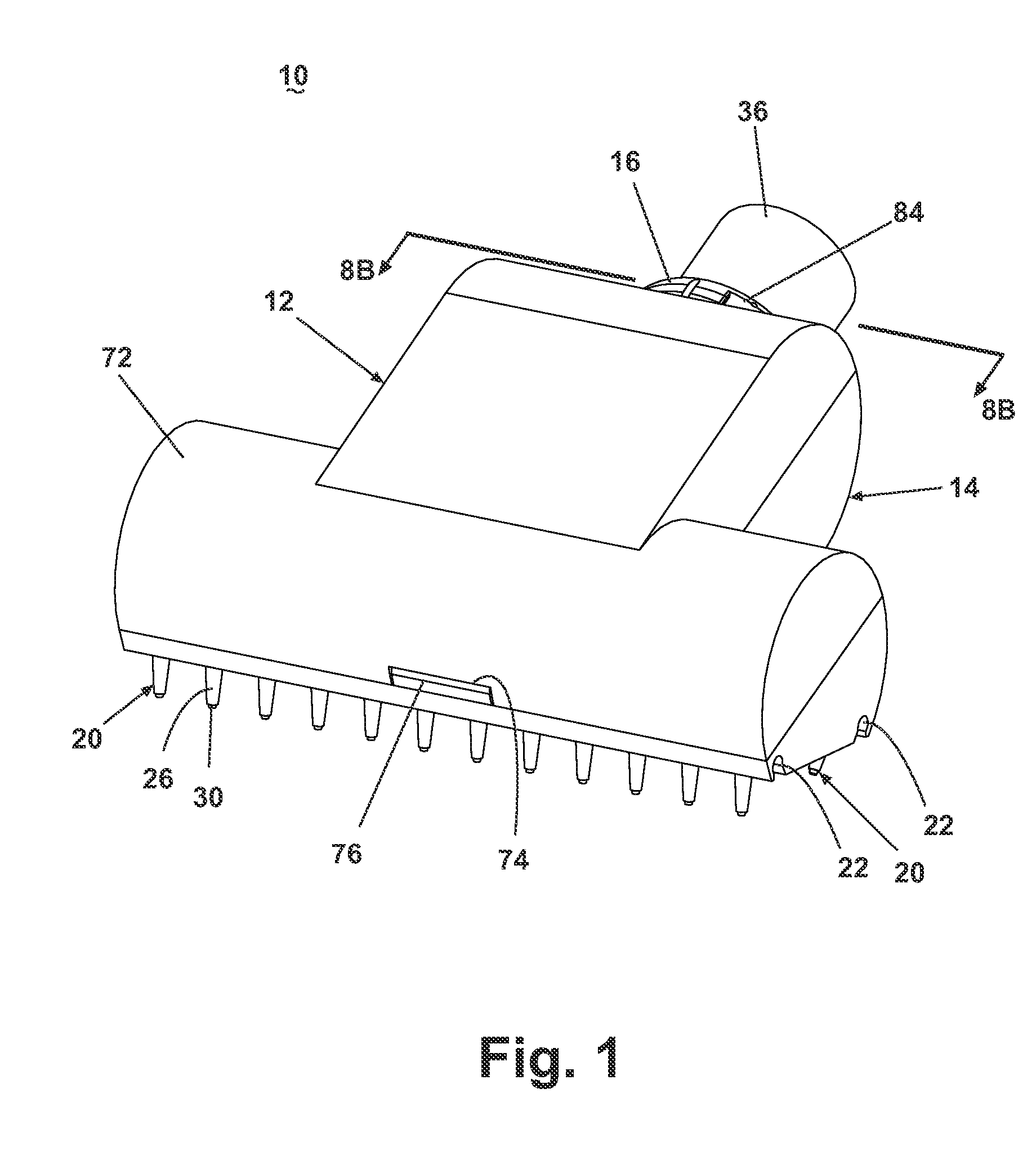
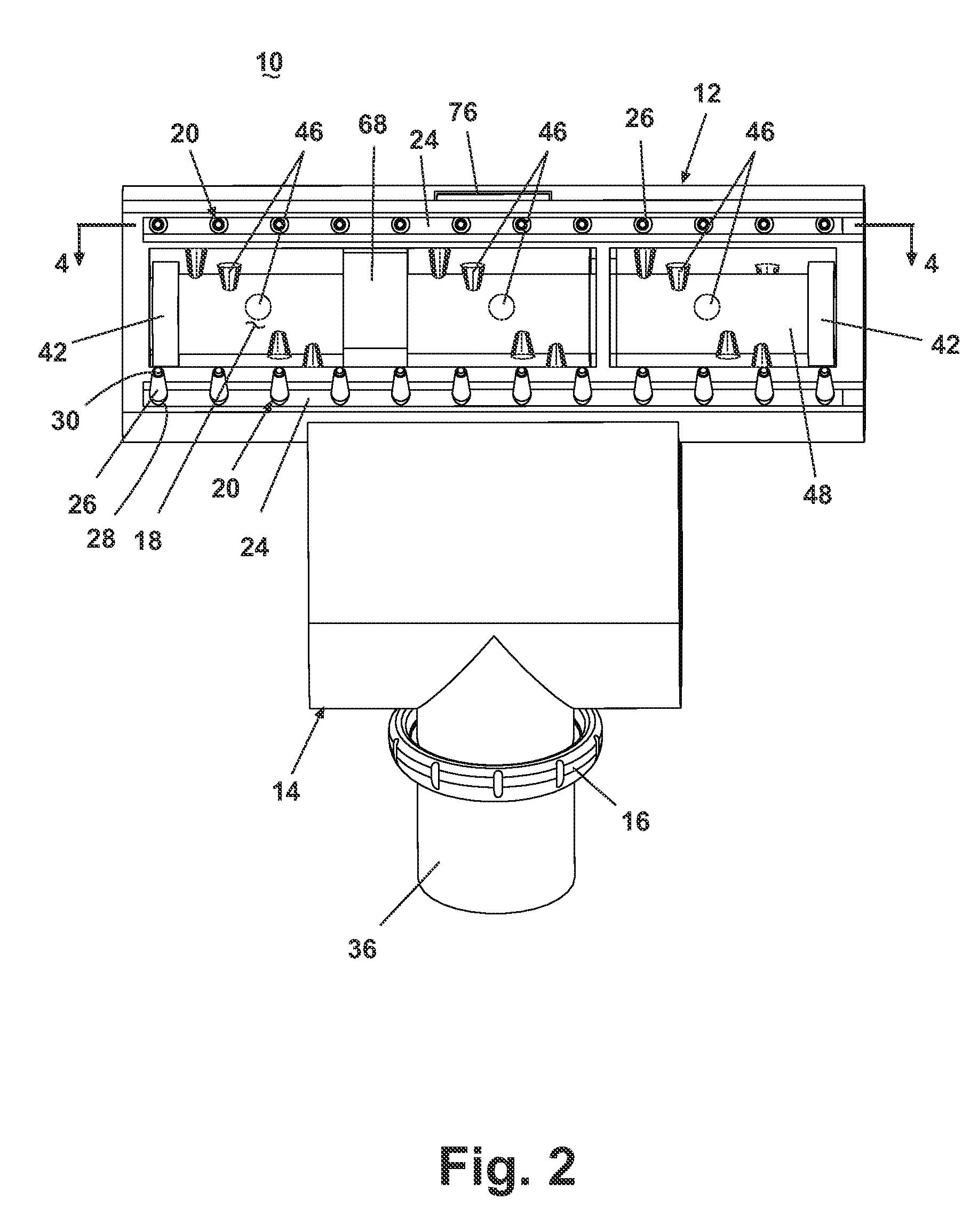
a vacuum cleaner and accessory technology, applied in vacuum cleaners, carpet cleaners, domestic applications, etc., can solve the problems of preventing hair and other debris, reducing and avoiding the battle of pet hair removal, so as to reduce the performance of the impeller assembly and prevent hair and other debris. , the effect of increasing the inertia
- Summary
- Abstract
- Description
- Claims
- Application Information
AI Technical Summary
Benefits of technology
Problems solved by technology
Method used
Image
Examples
second embodiment
[0049] the vacuum accessory tool 10 is illustrated in FIG. 9, where components similar to those of the embodiment described above are identified with like reference numerals. In this embodiment, the hair removal element 20 is overmolded directly onto the lower housing 14 adjacent to or partially overlapping the suction nozzle 18. As illustrated the vacuum accessory tool comprises three hair removal elements 20, two adjacent a forward side of the suction nozzle 18 and one adjacent a rearward side of the suction nozzle 18, however, it is within the scope of the invention to have any number or of hair removal elements in various positions relative to the suction nozzle 18.
third embodiment
[0050] the vacuum accessory tool 10 with an alternative hair removal assembly formed by a plurality of hair removal elements 100 is illustrated in FIGS. 10 and 11, where components similar to those of the embodiment described above are identified with like reference numerals. In this embodiment, each hair removal element 100 is an integrally molded structure comprising an elongated base 102 that terminates at a generally bulbous support 104 on both ends. A plurality of nubs or bristles 106 extend in a perpendicular manner from the base 102. At least the bristles 106 of the hair removal element 100 are formed of a flexible polymeric material so that an electrostatic charge builds on the bristles 106 when the hair removal element 100 moves relative to the carpet or other surface while in contact with the carpet or other surface as previously described. In the illustrated embodiment, the tool 10 comprises a plurality of the hair removal elements 100 mounted with the respective supports...
fourth embodiment
[0051] the vacuum accessory tool 10 with another alternative hair removal assembly 200 is illustrated in FIGS. 12 and 13, where components similar to those of the embodiment described above are identified with like reference numerals. In this embodiment, vacuum accessory tool 10 comprises a hair removal element 200 that is secured to the forward end of the nozzle body formed by the upper housing 12 and the lower housing 14. The working air conduit 36 is integrally formed with the upper housing 12 has a annular ring 202 that serves as a stop for a flexible hose that is connected to the working air conduit 36. The lower housing 14 has an arcuate cut-out 204 formed in the rear side of the housing 14 that mates with the working air conduit 36. The upper and lower housings 12, 14 further comprise a first and second annular groove 206, 208 that extend around the inner surfaces of the housings 12, 14 and which are formed near the forward end of the housings 12, 14. The first annular groove...
PUM
 Abstract
Description
Claims
Application Information
 - R&D
- Intellectual Property
- Life Sciences
- Materials
- Tech Scout
- Unparalleled Data Quality
- Higher Quality Content
- 60% Fewer Hallucinations
Browse by: Latest US Patents, China's latest patents, Technical Efficacy Thesaurus, Application Domain, Technology Topic, Popular Technical Reports.
© 2025 PatSnap. All rights reserved.Legal|Privacy policy|Modern Slavery Act Transparency Statement|Sitemap|About US| Contact US: help@patsnap.com


