Lean direct injection atomizer for gas turbine engines

a gas turbine engine and direct injection technology, applied in the ignition of turbine/propulsion engines, engine starters, lighting and heating apparatus, etc., can solve the problems of difficult to achieve the required performance levels, and the lean-burning system is prone to localized flame extinction and re-ignition, so as to increase the pressure and increase the pressure

Active Publication Date: 2006-11-09
ROLLS ROYCE PLC
View PDF8 Cites 121 Cited by
  • Summary
  • Abstract
  • Description
  • Claims
  • Application Information

AI Technical Summary

Benefits of technology

[0020] The subject invention is also directed to a method of managing airflow through the inner air circuit of a pre-filming air-blast atomizer which includes forming a flow passage of the inner air circuit, in an area downstream from a minimum area location thereof, in such a manner so that there is an increase in pressure from the minimum area location to a downstream exit of the inner air circuit, for air flows that remain attached to the walls of the passage. This method further includes confining the airflow exiting the inner air circuit within a conically expanding annular passage downstream from the minimum area location of the inner air circuit, and sizing the conically expanding annular passage to obtain a desired mass flow rate thro

Problems solved by technology

Acting in this manner, the pilot air cap will likely suffer thermal distress (i.e., oxidation, melting), and require some form of thermal management.
While the concept of the LDI system is sound, achieving the required levels of performance can be difficult.
Lean-burning systems are prone to localized flame extinction and re-ignition.
This results in combustion instability that can damage the combustion chamber.
Limitations i

Method used


Image

  • Lean direct injection atomizer for gas turbine engines
  • Lean direct injection atomizer for gas turbine engines
  • Lean direct injection atomizer for gas turbine engines

Examples


Embodiment Construction

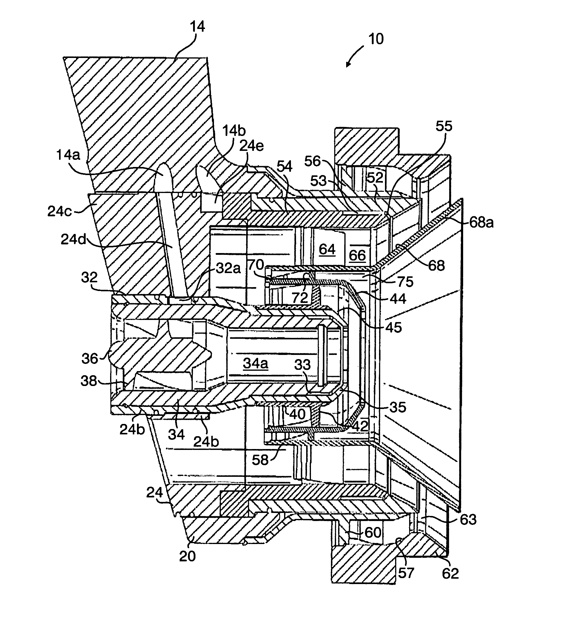
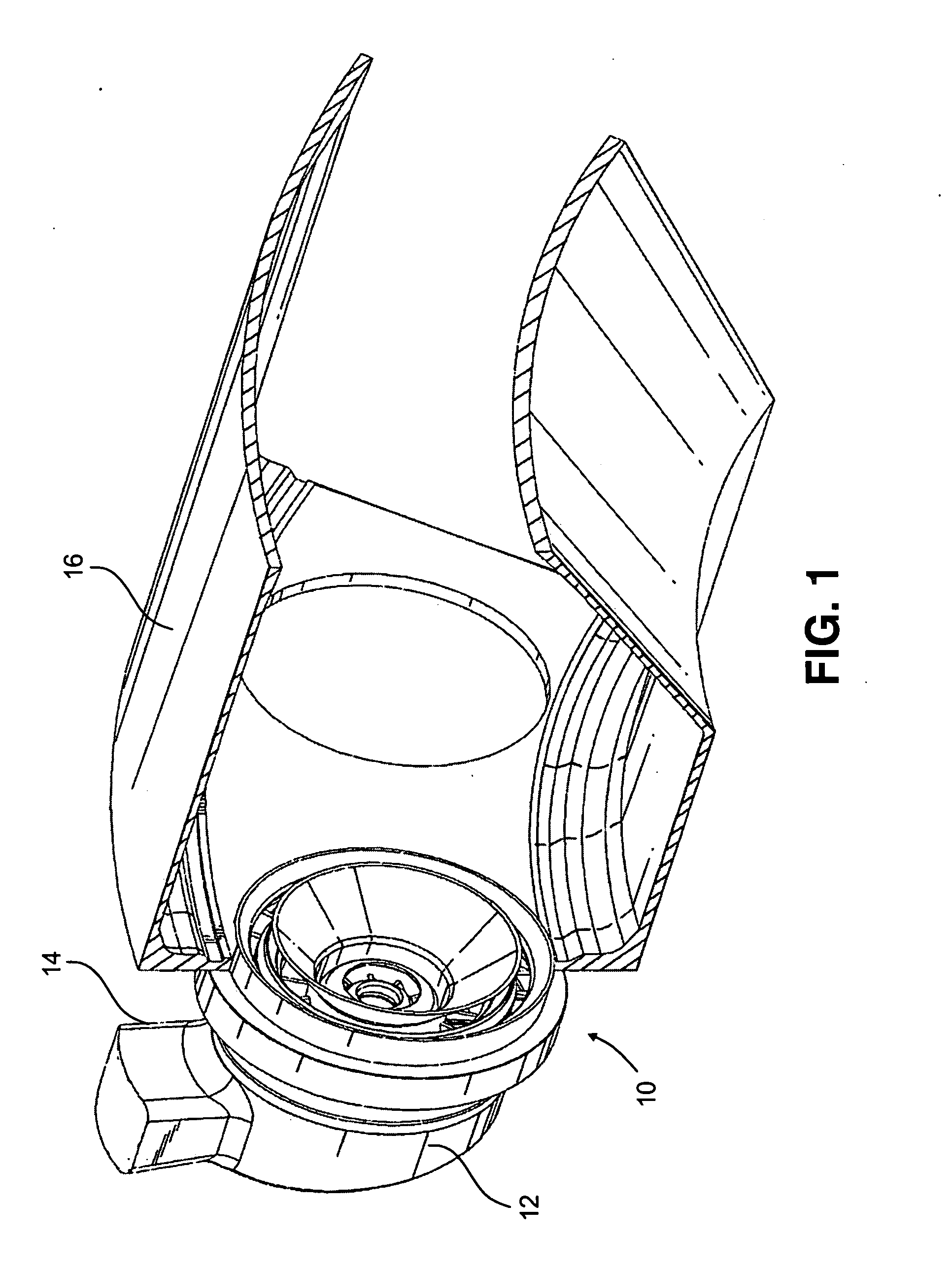
[0037] Referring now to the drawings wherein like reference numerals identify similar structural features or aspects of the subject invention, there is illustrated in FIG. 1 a fuel injector for a gas turbine engine, which is constructed in accordance with a preferred embodiment of the subject invention and designated generally by reference numeral 10. Fuel injector 10 is particularly adapted and configured to effectuate two-stage combustion within a gas turbine for enhanced operability and lean combustion for low pollutant emissions.

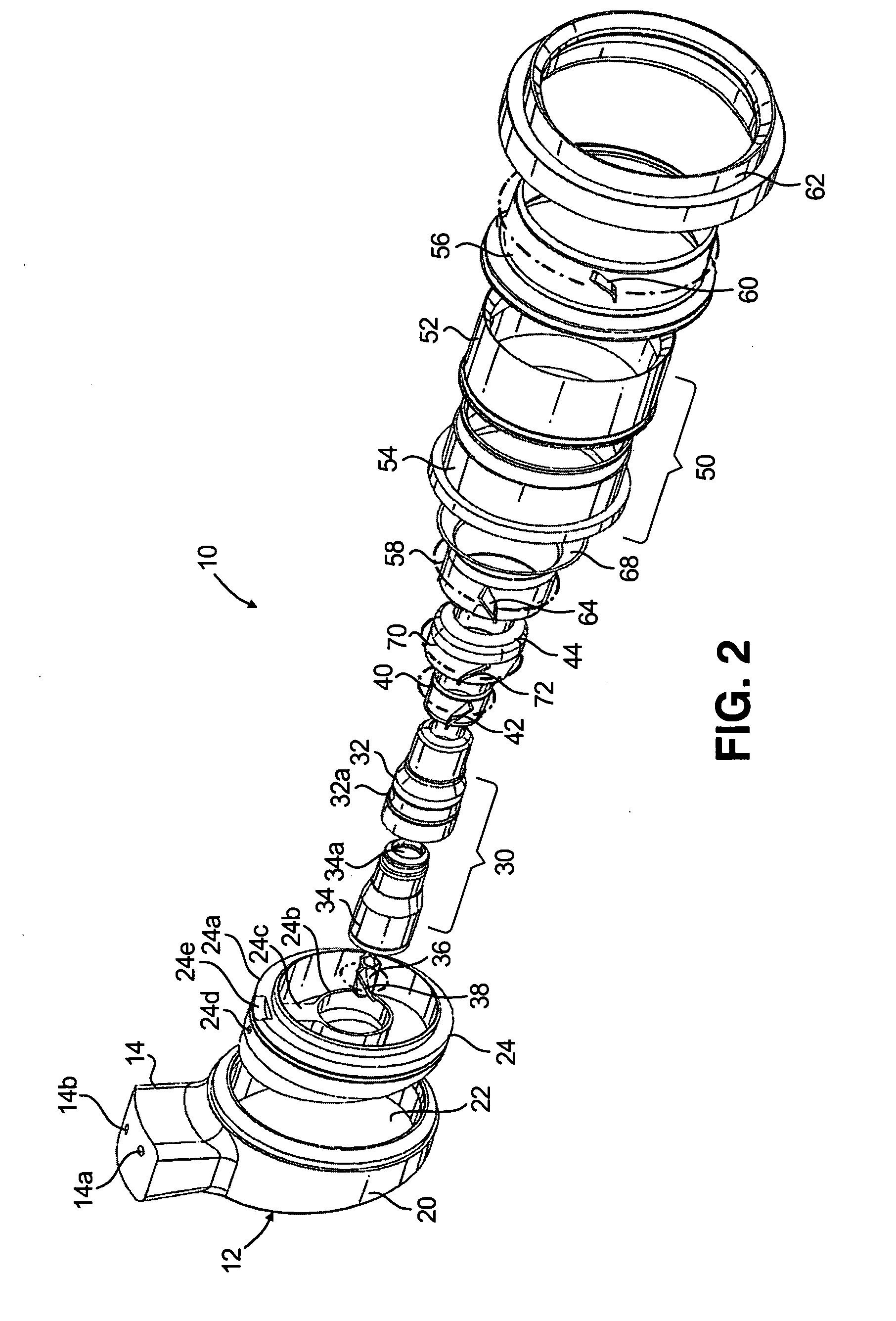
[0038] The fuel injector 10 consists of a pilot fuel delivery system and a main fuel delivery system integrated into a single fuel nozzle. The fuel nozzle is adapted and configured to mechanically and aerodynamically separate the combustion process into two radially staged zones: 1) a pilot combustion zone; and 2) a main combustion zone. During low power operation, only the pilot combustion zone is fueled (see FIG. 8). During high power operation, both ...


PUM


Abstract

A lean direct injection fuel nozzle for a gas turbine is disclosed which includes a radially outer main fuel delivery system including a main inner air swirler defined in part by a main inner air passage having a radially inner wall with a diverging downstream surface, an intermediate air swirler radially inward of the main inner air swirler for providing a cooling air flow along the downstream surface of the radially inner wall of the main inner air passage, and a radially inner pilot fuel delivery system radially inward of the intermediate air swirler.

Description

CROSS-REFERENCE TO RELATED APPLICATION [0001] This application claims the benefit of priority from U.S. Provisional Patent Application Ser. No. 60 / 677,757 filed May 4, 2005, the disclosure of which is herein incorporated by reference in its entirety.BACKGROUND OF THE INVENTION [0002] 1. Field of the Invention [0003] The subject invention is directed to gas turbines, and more particularly, to a system for delivering fuel to the combustion chamber of a gas turbine engine by lean direct injection. [0004] 2. Background of the Related Art [0005] With increased regulation of pollutants from gas turbine engines, a number of concepts have been developed to reduce engine emissions while improving engine efficiency and overall operability. One such concept is the use of staged combustion. Here, the combustion process is divided into two or more stages or zones, which are generally separated from each other, either radially or axially, but still permitted some measure of interaction. For examp...

Claims


Application Information

Patent Timeline
IPC IPC(8): F23R3/14
CPCF23D2900/11101F23R3/14F23R3/343F23R3/286F23R3/28
Inventor BUELOW, PHILIP E.O.WILLIAMS, BRANDON P.BRETZ, DAVID H.SPOONER, MICHAELMOHAMED, CAROLINEGILL, HELEN
Owner ROLLS ROYCE PLC
Why Eureka
Try Eureka