Systems and methods of power output measurement

a technology of power output measurement and system, applied in the direction of diagnostic recording/measuring, instruments, force/torque/work measurement, etc., can solve the problems of reducing power output, conventional heart rate measurement cannot accurately identify the increase in performance of athletes, and is not necessarily accurate assessment of the amount of work an individual is exerting. to achieve the effect of facilitating data transmission

Inactive Publication Date: 2006-11-09
SOULE
View PDF12 Cites 80 Cited by
  • Summary
  • Abstract
  • Description
  • Claims
  • Application Information

AI Technical Summary

Benefits of technology

[0009] The present invention pertains to systems and methods of individual power output measurement. One embodiment relates to a pressure sensing device configured to be mounted on the bottom surface of a shoe. The device includes a sensor, a wireless communication system, a housing, and a mounting system. A second embodiment relates to a direct power measurement system including a pressure sensing device, a computer module, and a display module. In a bicycling application of the system, the device is mounted on the bottom surface of a shoe so as to measure applied pressure between at least one of the rider's shoe and corresponding bicycle pedal. The computing module mathematically converts the measured pressure as a funct

Problems solved by technology

However, it has been determined that heart rate alone is not necessarily an accurate assessment of the amount of work an individual is exerting at any given time.
In this case, conventional heart rate measurement will not accurately identify an athlete's increased performance.
Likewise, a decrease in power output translates to a decreased athletic performance.
Unfortunately, it is difficult to accurately measure an athlete's power output.
In addition, few ath

Method used


Image

  • Systems and methods of power output measurement
  • Systems and methods of power output measurement
  • Systems and methods of power output measurement

Examples


Embodiment Construction

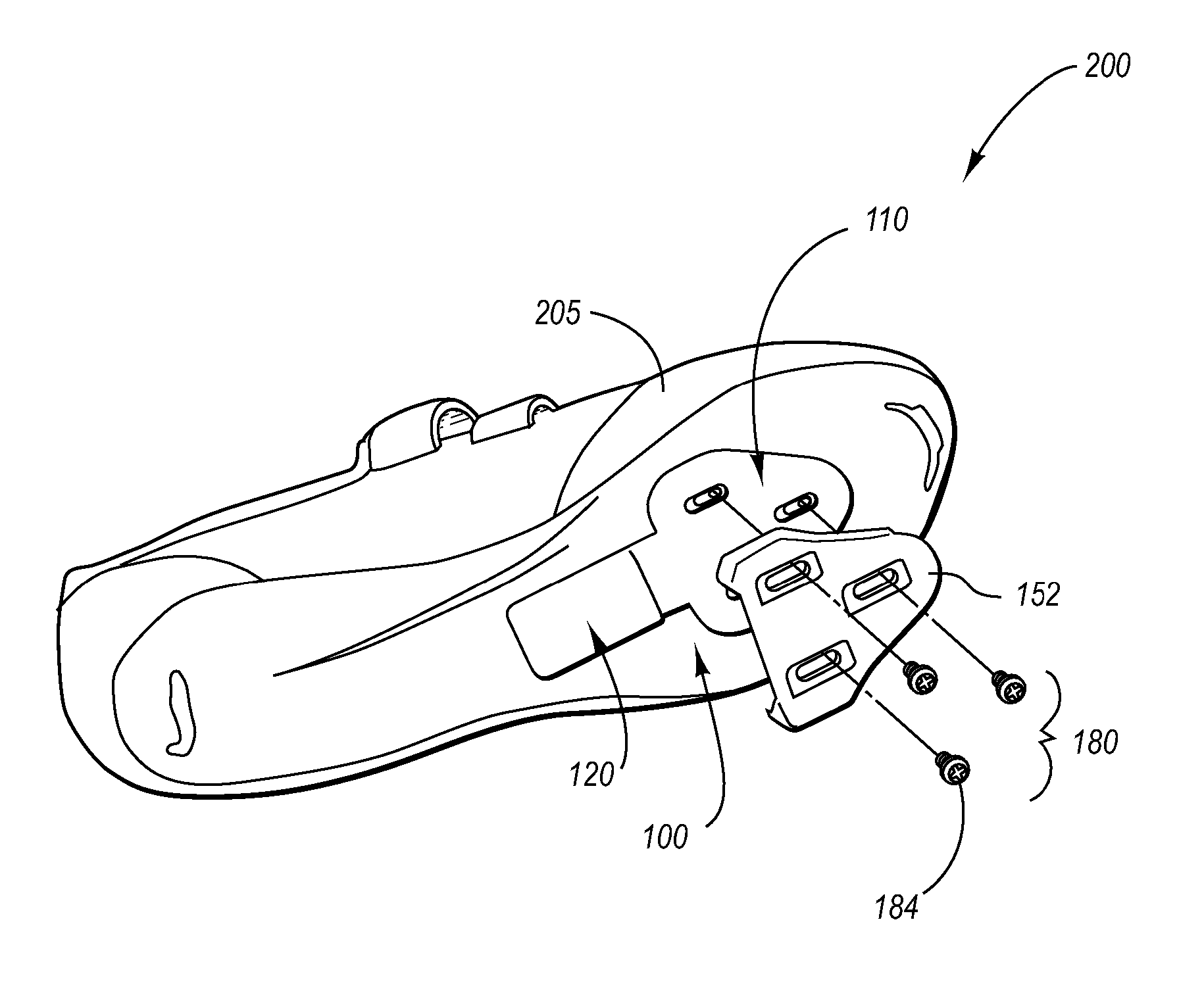
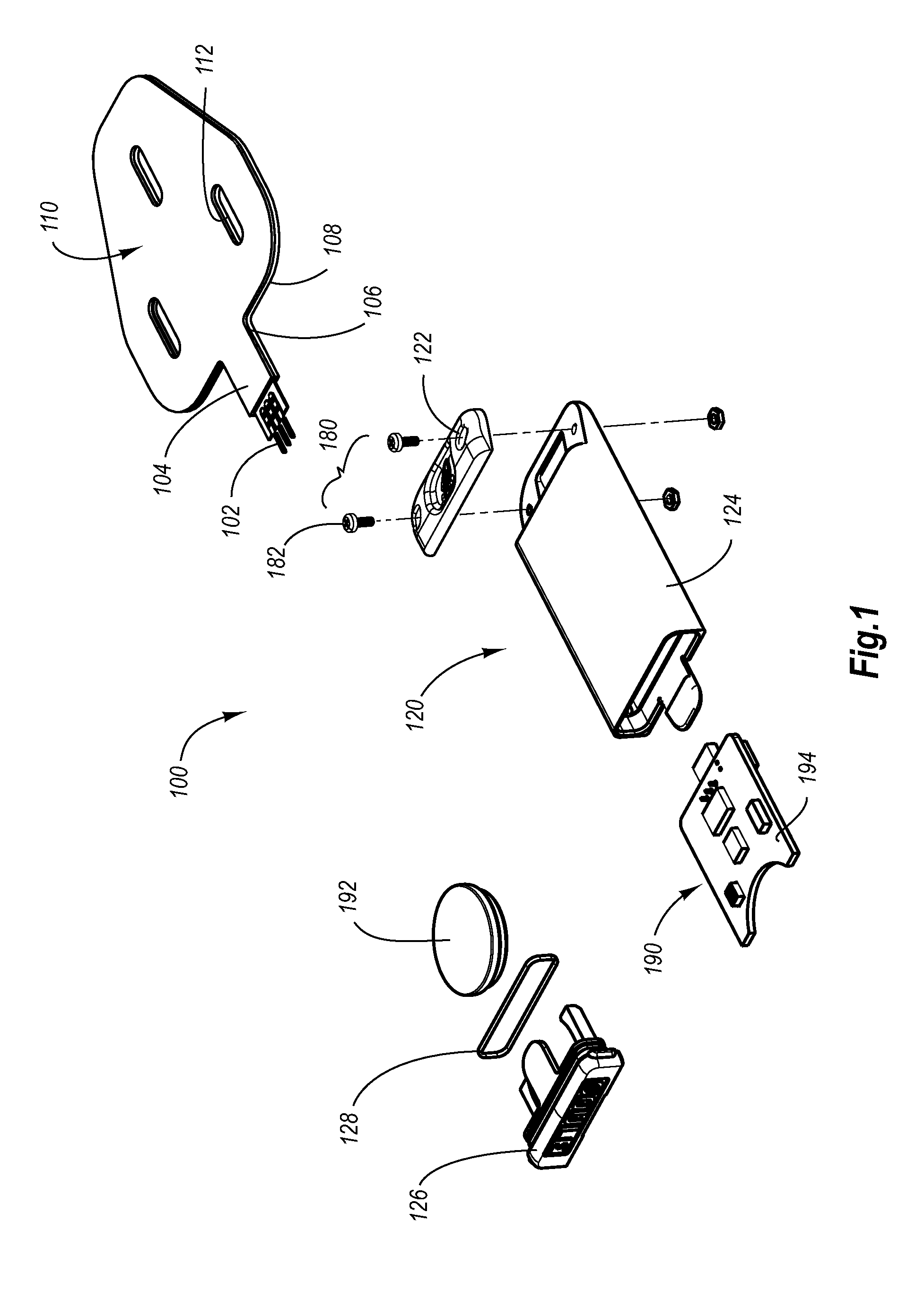
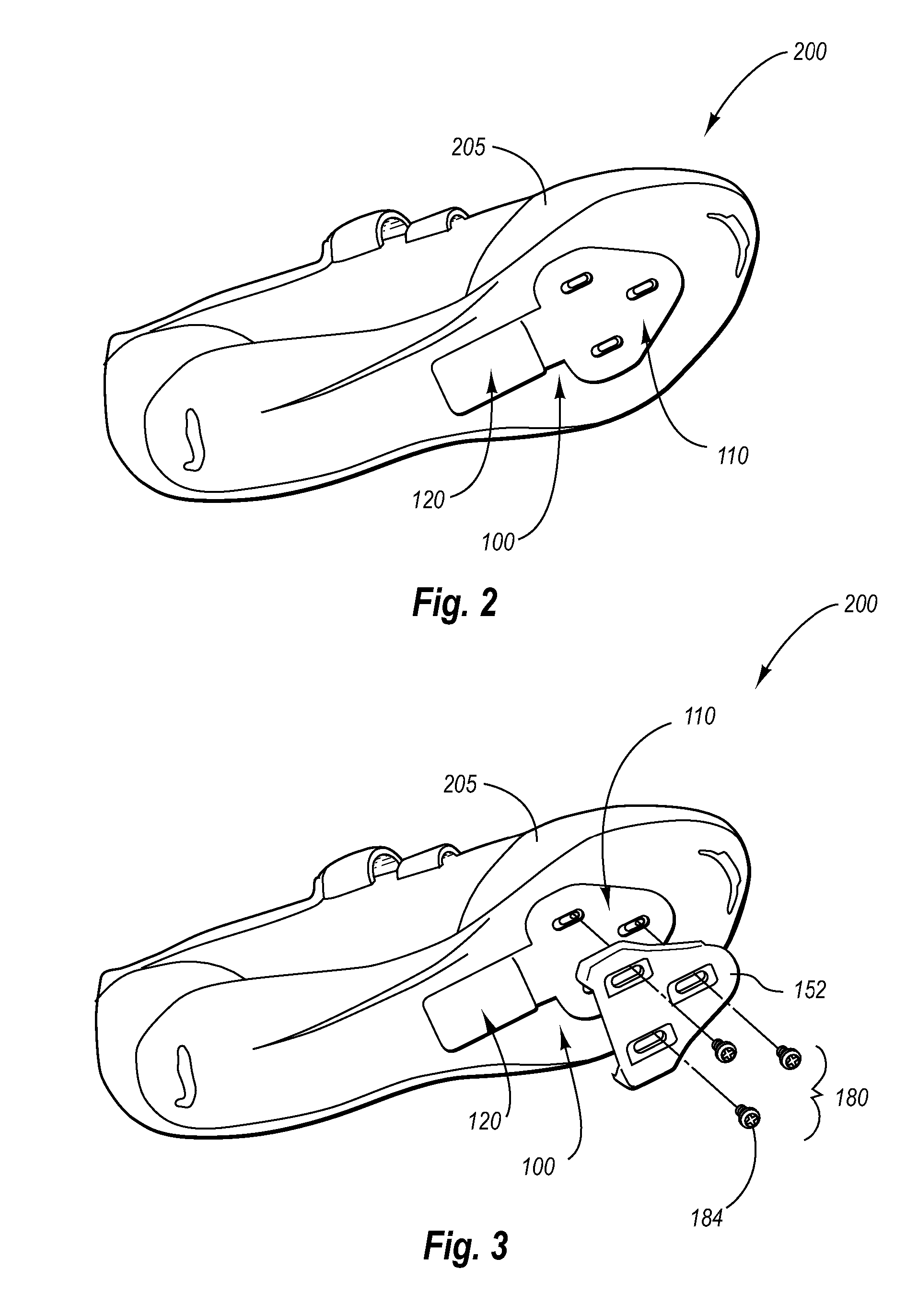
[0018] The present invention pertains to systems and methods of individual power output measurement. One embodiment relates to a pressure sensing device configured to be mounted on the bottom surface of a shoe. The device includes a sensor, a wireless communication system, a housing, and a mounting system. A second embodiment relates to a direct power measurement system including a pressure sensing device, a computer module, and a display module. In a bicycling application of the system, the device is mounted on the bottom surface of a shoe so as to measure applied pressure between at least one of the rider's shoe and corresponding bicycle pedal. The computing module mathematically converts the measured pressure as a function of time to a value of power exerted by the rider. In addition, the computing module may utilize the measured pressure as a function of time to compute the rider's cadence (pedal revolutions per unit of time). Various well-known communication systems such as RF ...


PUM


Abstract

The present invention pertains to systems and methods of individual power output measurement. One embodiment relates to a pressure sensing device configured to be mounted on the bottom surface of a shoe. The device includes a sensor, a wireless communication system, a housing, and a mounting system. A second embodiment relates to a direct power measurement system including a pressure sensing device, a computer module, and a display module. In a bicycling application of the system, the device is mounted on the bottom surface of a shoe so as to measure applied pressure between at least one of the rider's shoe and corresponding bicycle pedal. The computing module mathematically converts the measured pressure as a function of time to a value of power exerted by the rider. In addition, the computing module may utilize the measured pressure as a function of time to compute the rider's cadence (pedal revolutions per unit of time). Various well-known communication systems such as RF may be integrated within the device and computing module to facilitate data transmission. Similar systems may be used to calculate an individual's power output during other activities including but not limited to running, rowing, walking, etc. A third embodiment relates to a method for calculating individual power output during an athletic activity. The method includes sensing pressure at a particular location, calculating or computing power, and displaying power.

Description

RELATED APPLICATIONS [0001] This application claims priority to U.S. provisional application Ser. No. 60 / 678,887 filed May 6, 2005.BACKGROUND [0002] 1. Field of the Invention [0003] The present invention relates to systems and methods of power output measurement. In particular the present invention relates to a power measurement device. [0004] 2. Background of the Invention and Related Art [0005] Endurance athletes utilize various metrics to measure their performance and chart their workouts. These metrics are recorded and analyzed both during and after workouts. For example, interval type workouts typically involve multiple sets of intense activity, semi-intense activity, and rest. The intense activity may be characterized by a range of metrics which correlate to the desired intensity for a particular athlete. Likewise, the rest or semi-intense activity periods may be characterized by a range or metrics which correlate to the desired restful state for a particular athlete. One comm...

Claims


Application Information

Patent Timeline
IPC IPC(8): G01L5/04
CPCA61B5/0002A61B5/221G01L3/24A61B2562/0247A61B5/6807
Inventor WYATT, ROLAND JEFFREYSEGUIN, DYLAN JOHNKNAPP, RICHARD BENJAMIN
Owner SOULE
Why Eureka
Try Eureka