[0008] Accordingly, the invention is made in order to address the problem described above. It is an object of the invention to provide a compact and simply-structured manufacturing device for a synthetic resin hollow molded body for efficiently manufacturing a synthetic resin hollow molded body including three members, that are a first split assembly member, a second split assembly member and a third split assembly member. It is another object of the invention to provide a manufacturing method for a synthetic resin hollow molded body, for efficiently manufacturing a synthetic resin hollow molded body which includes the three members, that are the first split assembly member, second split assembly member, and the third split assembly members, and which has high flexibility in design.
[0010] According the aspect of the invention, in the manufacturing device for a synthetic resin hollow molded body, each of the contact portions of the three members contacts the corresponding contact portion when the dies are closed, and then each of the contact portions is jointed with the corresponding contact portion by the second injection. Thus, it is possible to efficiently manufacture the synthetic resin hollow molded body. Also, since the manufacturing device includes the ejecting mechanism, the sliding mechanism and the rotating mechanism, it is possible to realize a relatively compact and simply-structured manufacturing device.
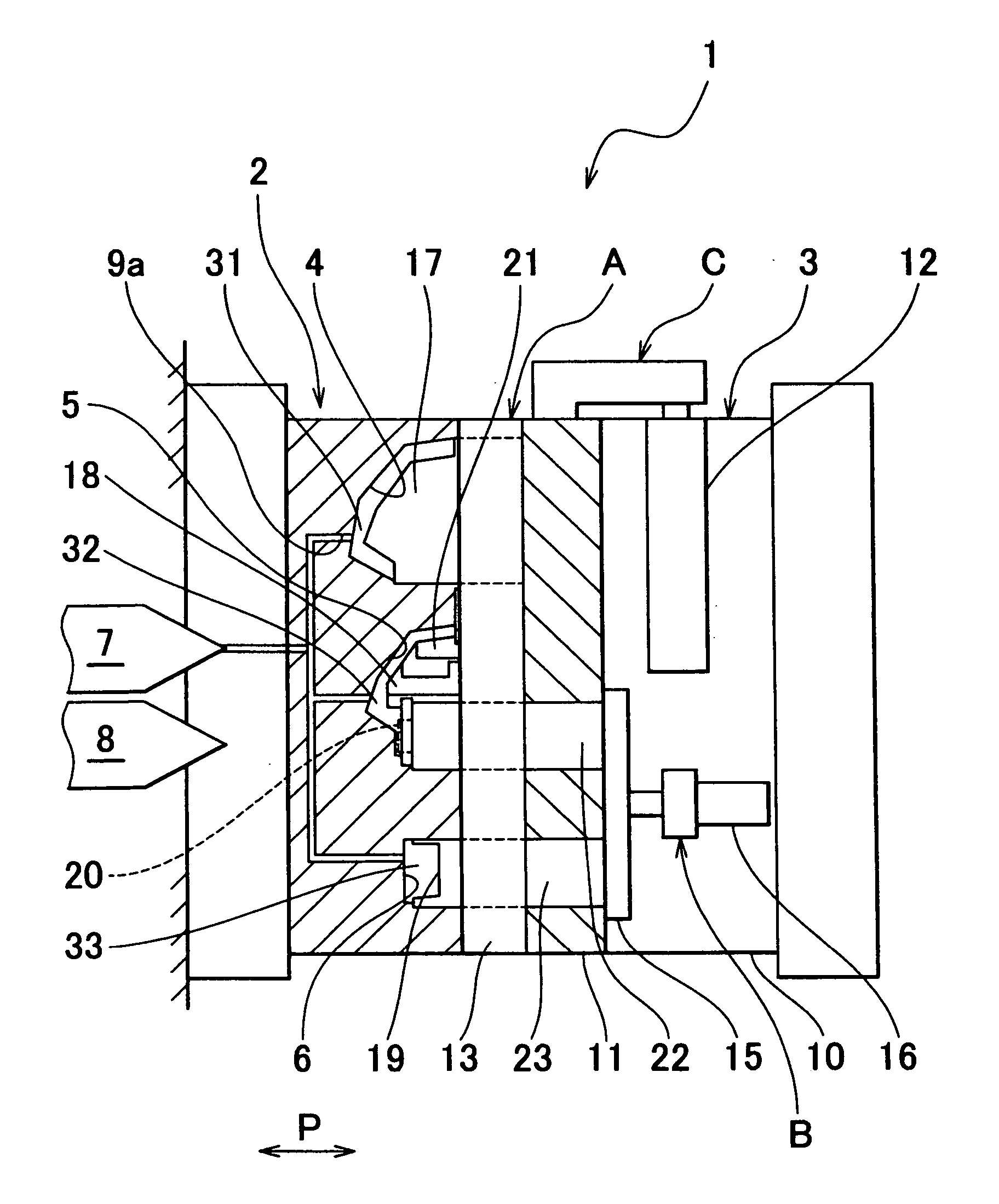
[0011] The sliding mechanism may include a sliding member which is supported by the second die body so as to be slidable in the direction perpendicular to the die opening / closing direction, and a slide driving portion which slides the sliding member. The ejecting mechanism may include an ejecting member which is supported by the sliding member so as to be movable in the die opening / closing direction, and an ejection driving portion which moves the ejecting member. The rotating mechanism may include a rotating member which is supported by the sliding member so as to be rotatable around the shaft center in the die opening / closing direction, and a rotation driving portion which rotates the rotating member. The first die may include a female die portion for molding the first split assembly member, a female die portion for molding the second split assembly member, and a female die portion for molding the third split assembly member. The sliding portion may include a male die portion for molding the first split assembly member. The ejecting member may include a male die portion for molding the second split assembly member. The rotating member may include a male die portion for molding the third split assembly member. Thus, it is possible to manufacture the synthetic resin hollow molded body more efficiently, and to realize a more compact and simply-structured manufacturing device.
[0012] The “rotating member” may include the female die portion for molding the third split assembly member and an insert die portion for molding the second split assembly member at rotationally symmetrical positions. Thus, it is possible to manufacture a synthetic resin hollow molded body having a more complex shape. The aforementioned “male die portion for molding the second split assembly member” may include a slide core which is slidable in a predetermined direction. Thus, it is possible to manufacture a synthetic resin hollow molded body having a more complex shape. In addition, the “first die” may include the male die portions arranged in the direction perpendicular to the die opening / closing direction. Thus, it is possible to manufacture a more compact and simply-structured manufacturing device.
[0013] According to an aspect of the invention, a manufacturing method for a synthetic resin hollow molded body includes a first
injection molding process, a positioning process and a second
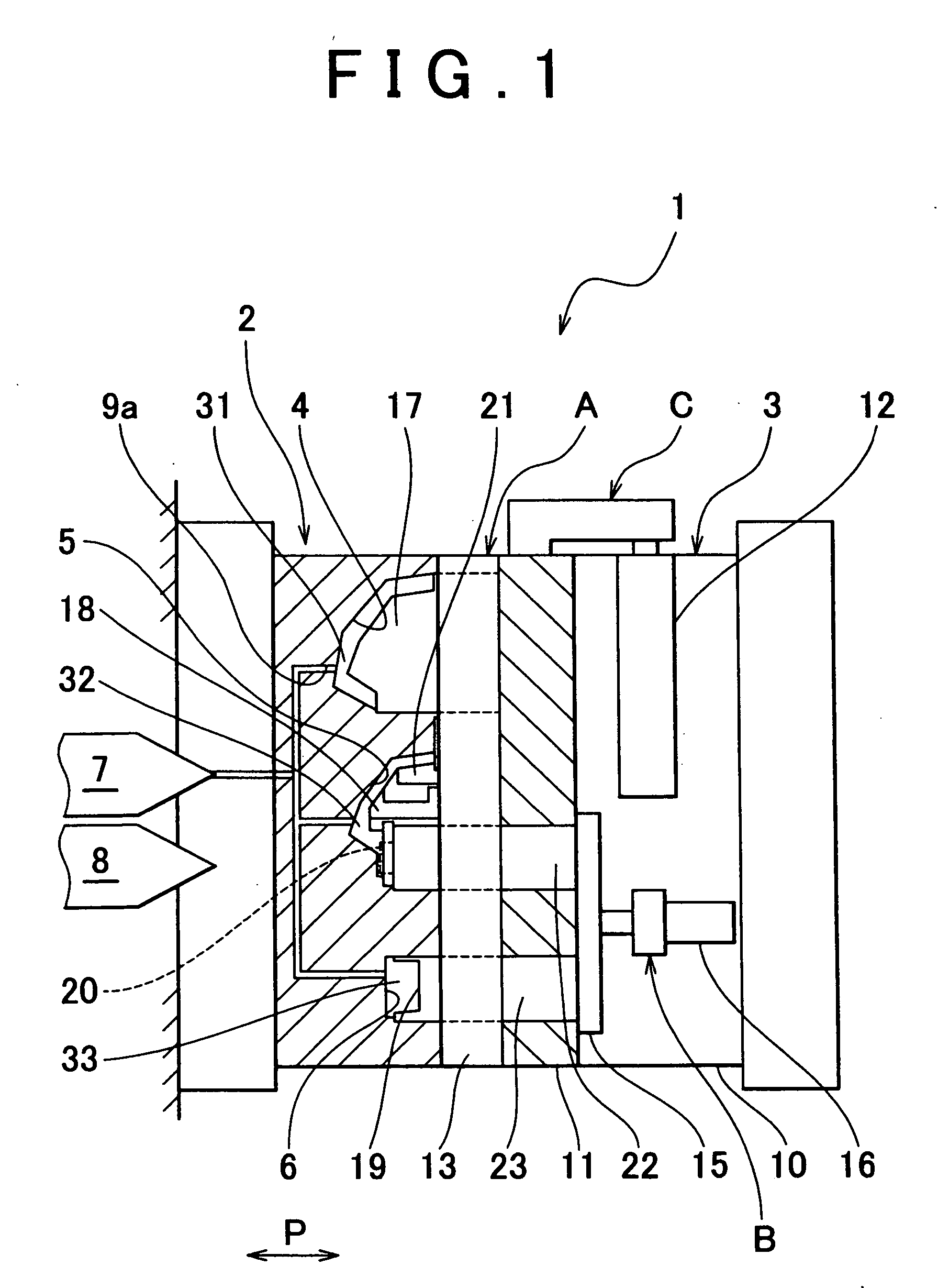
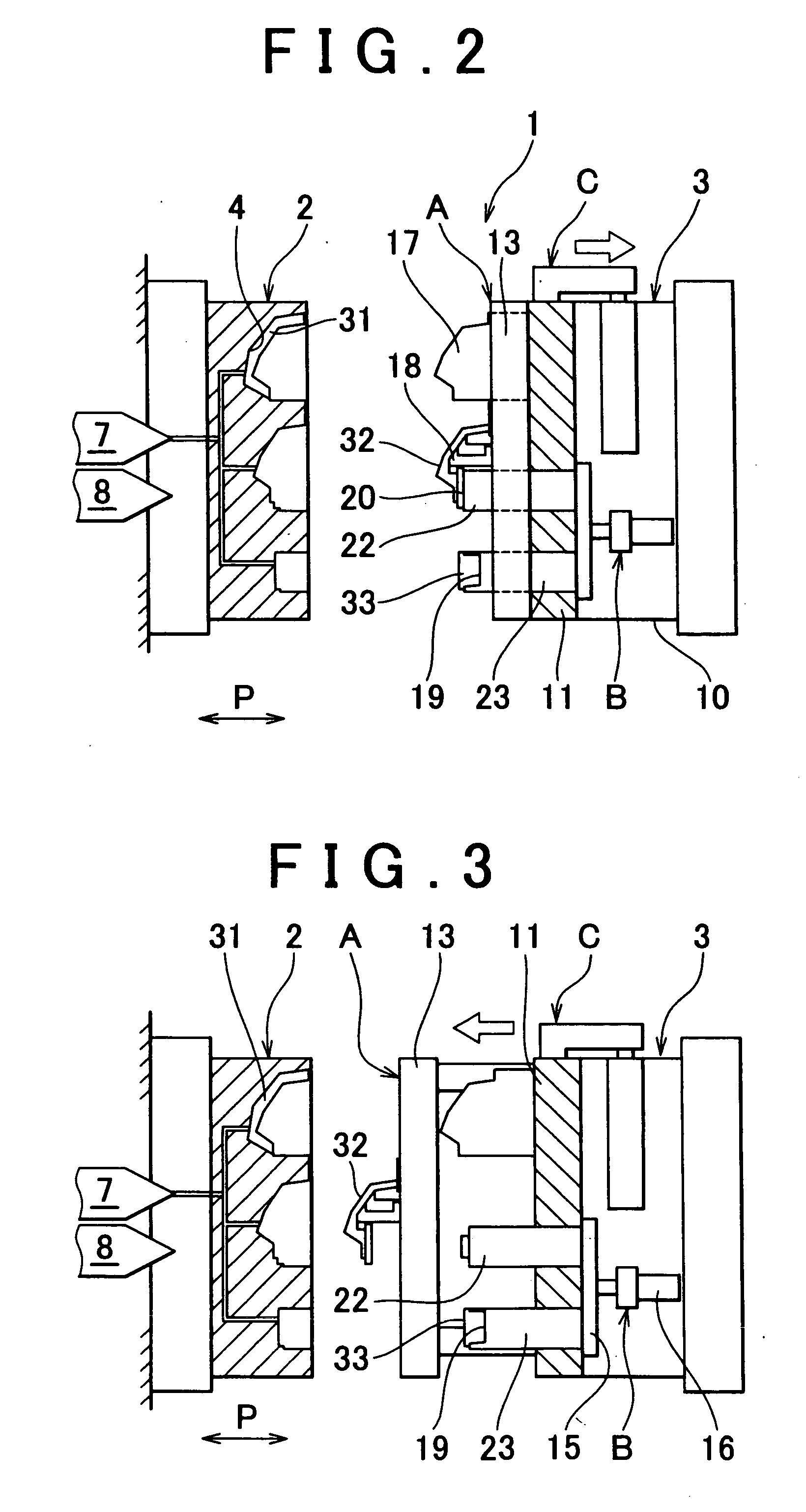
injection molding process. In the first injection molding process, a first split assembly member, a second split assembly member and a third split assembly member are molded by a first injection between a first die and a second die. In the positioning process, phases of the first split assembly member, second split assembly member, and the third split assembly member are made different in a die opening / closing direction, and then first split assembly member, second split assembly member, and the third split assembly member are made to face one another in the die opening / closing direction while the first die and the second die are open. In the second injection molding process, each of the contact portions of the first split assembly member, second split assembly member, and the third split assembly member is made to contact the corresponding contact portion and each of the contact portions is jointed with the corresponding contact portion by a second injection between the first die and the second die. Thus, it is possible to manufacture the synthetic resin hollow molded body including the three members, which are the first split assembly member, second split assembly member, and the third split assembly member, only by the injection molding process. Accordingly, it is possible to manufacture the synthetic resin hollow molded body more efficiently than when the synthetic resin hollow molded body is manufactured through the injection molding process and vibration
welding process. In addition, flash or the like is not generated, which makes it possible to manufacture a synthetic resin hollow molded body having higher flexibility in design and the like.
[0014] In the positioning process, the first split assembly member, second split assembly member, and the third split assembly member may be made to face one another in the following manner. The second split assembly member is moved in the die opening / closing direction such that the phases of the first split assembly member, second split assembly member, and the third split assembly member are made different in the die opening / closing direction. Then, the third split assembly member is rotated around the shaft center in the die opening / closing direction such that second split assembly member, and the third split assembly member face each other in the die opening / closing direction. Then, second split assembly member, and the third split assembly member are slid in the direction perpendicular to the die opening / closing direction. Thus, it is possible to manufacture the synthetic resin hollow molded body having a higher flexibility in design more efficiently.

