Eureka AIR delivers breakthrough ideas for toughest innovation challenges, trusted by R&D personnel around the world.

Voltage to current to voltage cell voltage monitor (VIV)

Inactive Publication Date: 2006-11-09
SAFT GRP SA
View PDF6 Cites 15 Cited by
  • Summary
  • Abstract
  • Description
  • Claims
  • Application Information

AI Technical Summary

Problems solved by technology

Accordingly, the efficiency of a circuit may be diminished due to less than optimal charging of each of individual cells.
However, monitoring circuits based upon differential amplifiers and resistor divider circuits suffer from excessive current draw as the number of cells are added to the series string increases, thereby resulting in higher background energy losses.
In many applications, such excessive current draw leads to substantial reduction in the operating time of battery powered circuits.
Thus, the efficiency of the device may be decreased.
In addition, measuring circuits which utilize resistors connected in a plurality of resistor divider networks suffer from accuracy errors due to attenuation of the measurement signal which reduces resolution in measuring the signal.
Therefore, resistor divider measuring circuits are unable to accurately determine small deviations in voltage levels of the individual cells.
Further, commercially available amplifiers and multiplexors which are used in conventional monitoring circuits are limited by the supply voltage which must be provided from the cells in order to operate the devices.
Also, conventional approaches suffer from a lack of accuracy when the offset voltage varies.
Thus, increased offset voltage levels resulting from a large number of series connected cells may give rise to an increasing error in the measured voltage.
Measurement error also results in conventional approaches due to variations in operating temperature of the measurement circuit.
However, this approach raises the cost of the components in the measurement circuit because of the increased number of microprocessors for each of the smaller modules and reduces the ability to build standalone cell batteries which have a series connection of 16 cells or more.

Method used


Image

  • Voltage to current to voltage cell voltage monitor (VIV)
  • Voltage to current to voltage cell voltage monitor (VIV)
  • Voltage to current to voltage cell voltage monitor (VIV)

Examples


Embodiment Construction

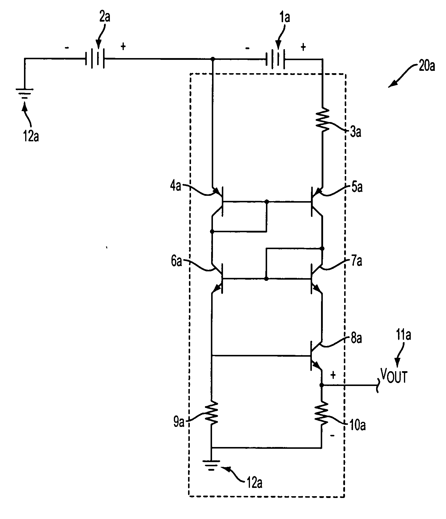
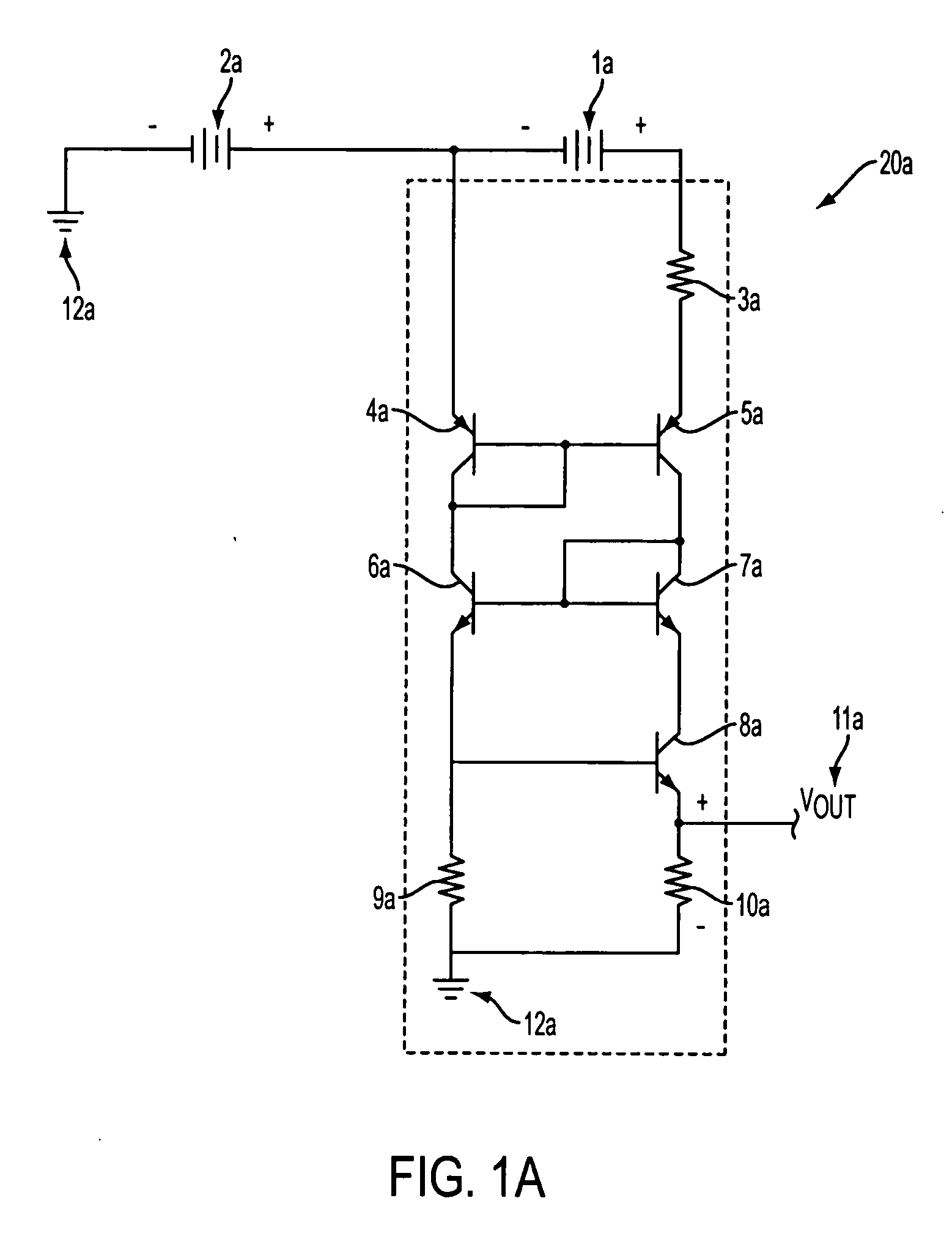
[0020] An exemplary embodiment of the voltage measurement circuit is described below with reference to FIG. 1a. The circuit depicted in FIG. 1a includes a measurement module 20a which accurately determines the voltage of a first voltage source 1a which is connected in series with an offset voltage source 2a. Thus, an output voltage is provided which is proportional to the voltage of first voltage source 1a without the offset voltage created by offset voltage source 2a. By virtue of the series connection of voltage sources 1a and 2a, the voltage of offset voltage source 2a is added to the voltage of first voltage source 1a. Thus, the voltage potential established between the positive terminal of first voltage source 1a and ground is the sum of the independent voltages of first voltage source 1a and offset voltage source 2a.

[0021] The measurement module 20a generally comprises a first resistor 3a which is connected to a first terminal (positive terminal) of first voltage source 1a. T...


PUM


Abstract

A voltage measurement circuit is provided which converts a voltage of a first voltage source connected in series with an offset voltage source to an output voltage, including first and second current mirrors for accurately measuring voltage so as to provide a proportional output voltage with the offset voltage removed. Further, voltage measurements can be precisely determined for each of a plurality of voltage sources, such as a plurality of electrochemical cells in a series electrical connection. By virtue of the voltage measurement circuit, the effect of different offset voltage values on the measured voltage is minimized. Also, the voltage measurement circuit exhibits enhanced stability to variations in operating temperature. Accordingly, accuracy of voltage measurements where offset voltages are present is improved.

Description

BACKGROUND OF THE INVENTION [0001] 1. Field of the Invention [0002] Apparatuses and methods consistent with the present invention relate to measurement of voltage levels of voltage sources involving conversion of voltage values. [0003] 2. Description of the Related Art [0004] In voltage measurement applications, a voltage which is monitored may include an offset voltage from an offset voltage source, such as where a plurality of electrochemical cells are connected in series. By connecting a plurality of electrochemical cells in this manner, the voltage of each of the individual cells is added. Accordingly, the total voltage of the series connected electrochemical cells may be provided as a power source for applications where the desired voltage exceeds the voltage of an individual cell. [0005] Further, many applications require operating voltages that are significantly higher than the voltage of a single cells. In these applications, numerous individual electrochemical cells may be ...

Claims


Application Information

Patent Timeline
IPC IPC(8): H03K5/22
CPCG01R19/2503
Inventor SACK, THOMAS T.HOFFMAN, PHILIP K.
Owner SAFT GRP SA
Why Eureka
Eureka Blog
Learn More