Selectable subreflector configurations for antenna beam reconfigurability

Inactive Publication Date: 2006-11-09
SPACE SYST LORAL INC
View PDF5 Cites 6 Cited by
  • Summary
  • Abstract
  • Description
  • Claims
  • Application Information

AI Technical Summary

Benefits of technology

[0011] An exemplary antenna system comprises a main reflector and at least one feed element. The feed element illuminates a selected one of a plurality of subreflectors and the selected subreflector illuminates the main reflector. Each of the plurality of subreflectors has a different surface contour shape for configuring the rays of radiation from the feed element into a beam of desired cross-sectional configuration corresponding to the desired antenna beam coverage pattern. The positioning mechanism provides for the positioning of any selected one of the plurality of subreflectors so that it is illuminated by the feed element and illuminates the main reflector. Preferably, the positioning mechanism is capable of multiple actuations so that the antenna beam coverage pattern may be changed from time to time as the satellite operator desires, and to facilitate system testing.
[0013] In accordance with a preferred embodiment of the invention, the surface contour of the main reflector is also shaped to optimize overall antenna system performance taking into account the surface contours of each of the plurality of subreflectors.
[0014] In a preferred embodiment of the invention, the main reflector is separately pivotable with respect to the subreflector, thereby providing additional capability to adjust the direction of the antenna beam pattern.

Problems solved by technology

A disadvantage of this prior system is that for each desired antenna beam coverage pattern, a separate feed array and appropriate switching electronics is required.
A disadvantage of this technique is that it requires multiple feed elements and expensive and complex electronics.
Still other methods of reconfiguring antenna beam pattern by way of active phased array antennas are known in the art and present similar difficulties with respect to cost and complexity.

Method used


Image

  • Selectable subreflector configurations for antenna beam reconfigurability
  • Selectable subreflector configurations for antenna beam reconfigurability
  • Selectable subreflector configurations for antenna beam reconfigurability

Examples


Embodiment Construction

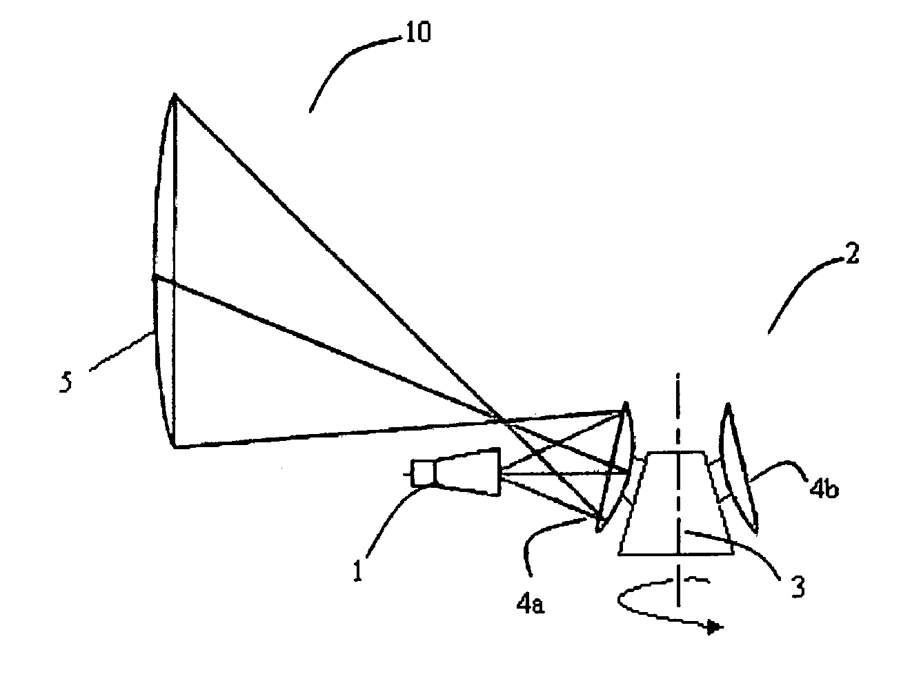
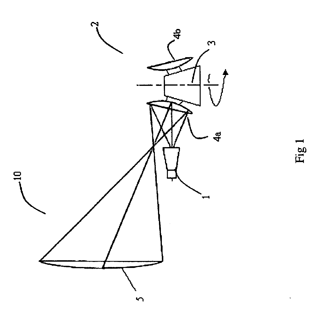
[0018]FIG. 1 shows an antenna system 10 employing an exemplary feed element 1, subreflector module 2 and main reflector 5 in accordance with the principles of the present invention. The subreflector module further comprises a plurality of subreflectors and a positioning mechanism 3. The mechanical configuration of the positioning mechanism is not relevant to this invention: it can be a rotary mechanism as shown in FIG. 1 or any other preferably simple, reliable mechanism known to those skilled in the art. By way of example, FIG. 1 illustrates an embodiment of the invention in which is provided two subreflectors, 4a and 4b, but it is to be understood that any number of subreflectors greater than one may be employed without departing from the principle of the present invention.

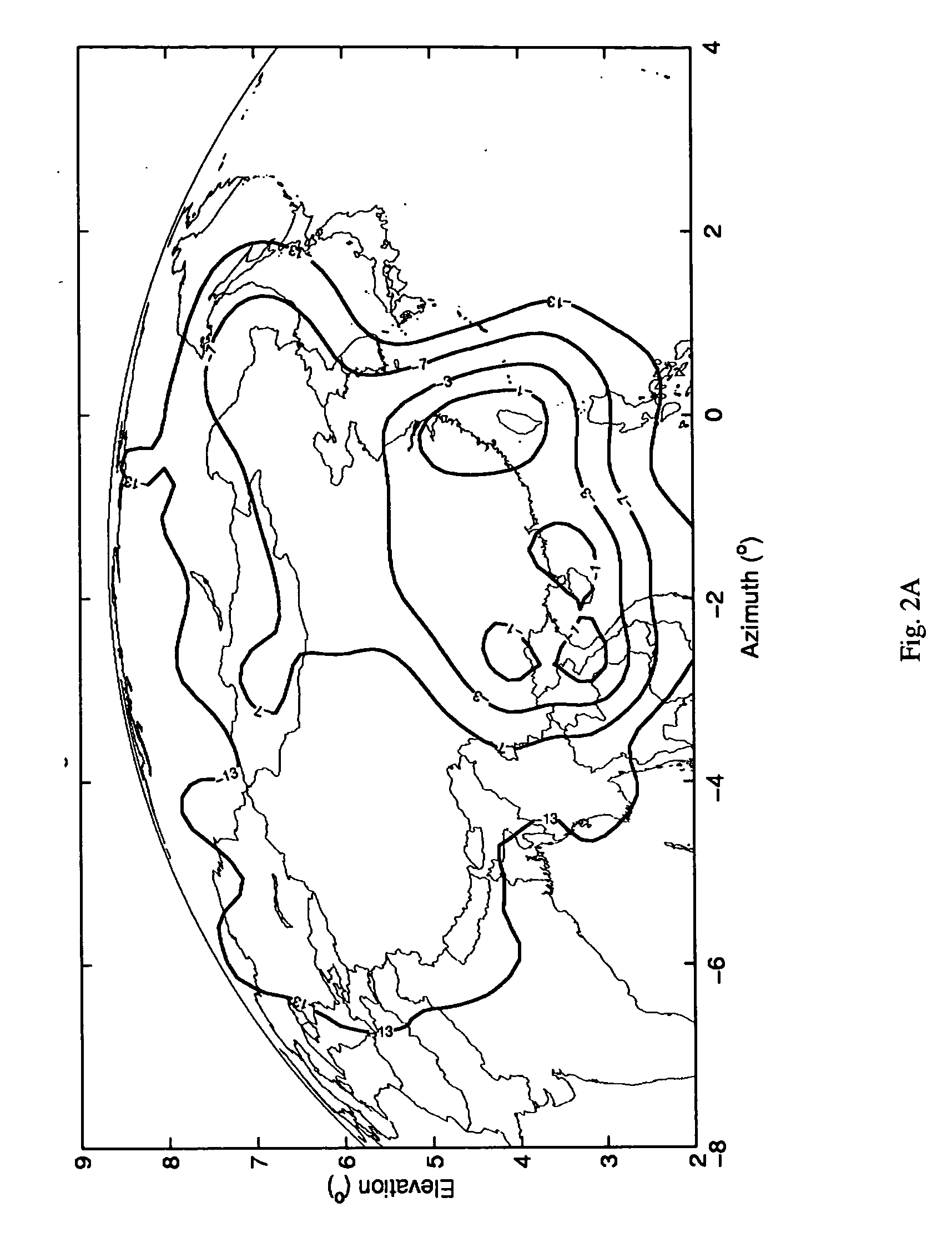
[0019]FIG. 2A illustrates an exemplary antenna beam coverage pattern provided when feed element 1 illuminates subreflector 4a which illuminates main reflector 5.

[0020]FIG. 2B illustrates an exemplary antenna b...


PUM


Abstract

An antenna system for producing selectively reconfigurable antenna beam coverage patterns suitable for use in on an earth orbiting spacecraft is described. The system comprises a main reflector and a feed element with a subreflector module on which are disposed one or more subreflectors. The subreflector module is selectably positionable such that any one of the subreflectors may be disposed such that it is illuminated by the feed element and illuminates the main reflector. Each of the subreflectors has a shaped surface corresponding to a desired antenna beam coverage beam pattern. By appropriate selection from among the plurality of subreflectors, any one of a plurality of antenna beam coverage patterns can by provided with a single feed element and single main reflector.

Description

BACKGROUND OF THE INVENTION [0001] 1. Field of the Invention [0002] This invention relates to multiple reflector antenna systems and methods for providing selectively reconfigurable antenna beam coverage patterns and, more particularly, to a reflector antenna system having a main reflector illuminated by a selected one of a plurality of subreflectors, and wherein each one of the plurality of subreflectors has a differently shaped surface contour so as to provide a different antenna beam coverage pattern, and wherein the plurality of subreflectors are mounted on a positioning mechanism providing the capability to reconfigure the antenna beam coverage pattern by changing the selected one of the plurality of subreflectors. [0003] The assignee of the present invention manufactures and deploys communications satellites. The assignee's typical customer often is an operator of a fleet comprising multiple satellites operating in geosynchronous orbit. Some of the satellites in such a fleet c...

Claims


Application Information

Patent Timeline
IPC IPC(8): H01Q13/00
CPCH01Q1/288H01Q19/192H01Q3/20H01Q3/12
Inventor SMITH, TERRY MCCREACLAUSSING, KARL ROBERTYI, JACK LI
Owner SPACE SYST LORAL INC
Why Eureka
Try Eureka