

Dynamic pressure bearing apparatus
a technology of dynamic pressure and bearings, which is applied in the direction of bearings, shafts and bearings, rotary bearings, etc., can solve the problems of reducing the life of bearings, foreign matters, and reducing the joint strength of thrust plates b>3/b>, so as to improve the dynamic pressure characteristic, and ensure the effect of good bearing li
- Summary
- Abstract
- Description
- Claims
- Application Information
AI Technical Summary
Benefits of technology
Problems solved by technology
Method used
Image

Examples
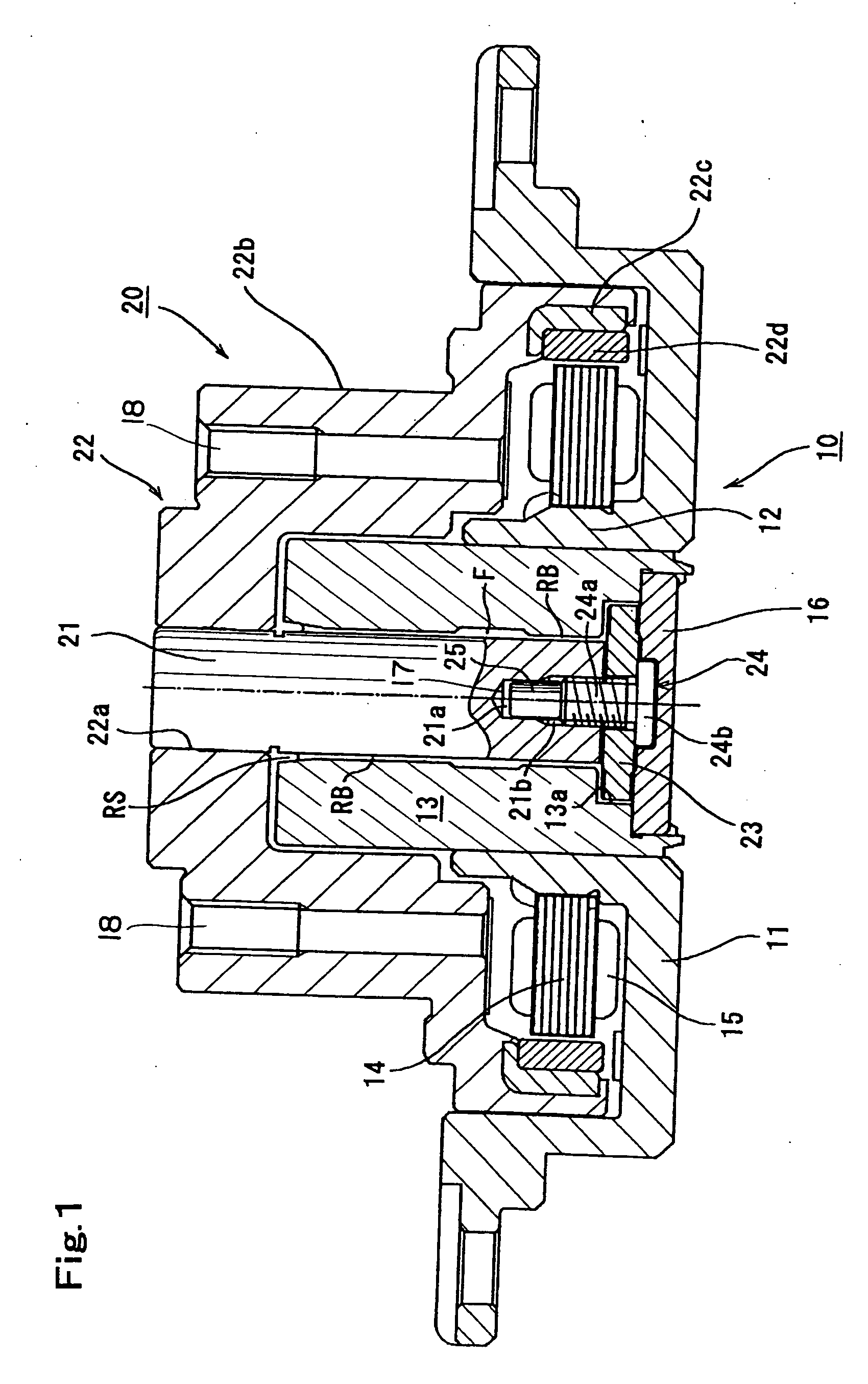
first embodiment
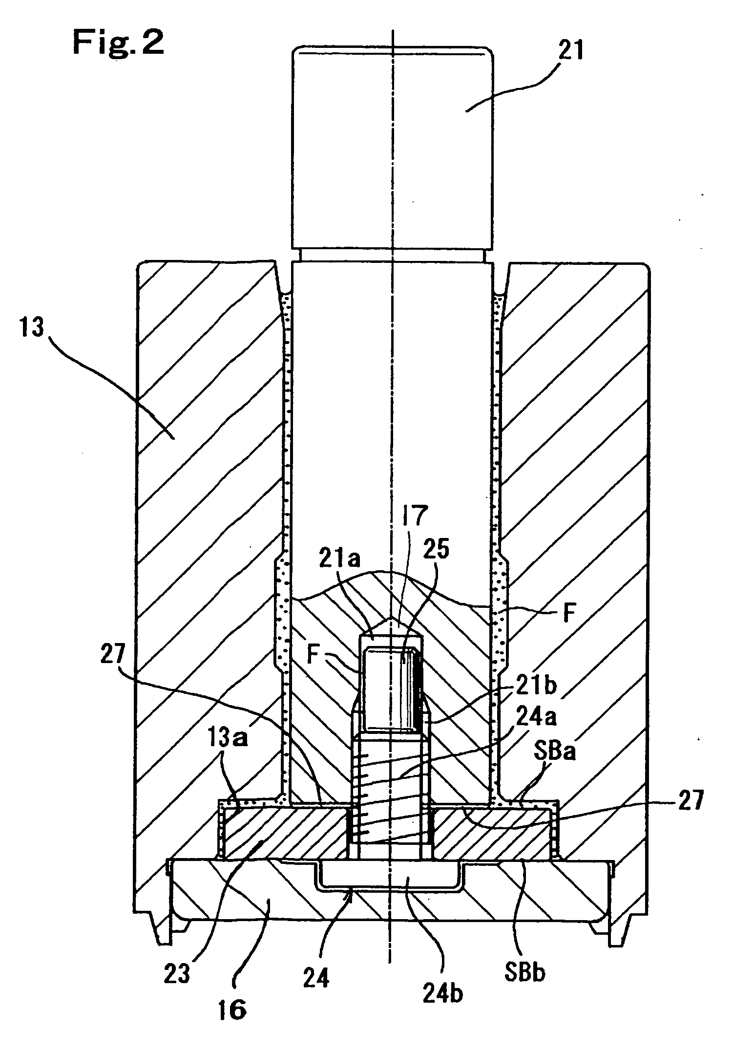
[0070] Although this embodiment can obtain the same effects / advantages as those in the first embodiment, it is possible to obtain the stable dynamic pressure characteristic in movement of the lubricating fluid F through the communication hole 37 even if a pressure difference is generated between both thrust bearing portions SBa and SBb in rotation of the motor by the communication hole 37.
[0071] Furthermore, FIG. 4 shows a third embodiment. In this embodiment, the injection path 27 is provided on the lower end surface of the shaft 21 like each of the foregoing embodiments. In addition to this, an injection path 47 consisting of a groove having the same shape as that of the injection path 27 is formed on the surface of the thrust plate 23 which comes into contact with the head portion 24b of the plate fixing screw 24. Moreover, both injection paths 27 and 47 are constituted so as to also function as the communication hole 37 (see FIG. 3) in the second embodiment.
[0072] That is, both...
eighth embodiment
[0084]FIG. 13 shows an In this embodiment, a screw hole for the plate fixing screw 24 is provided by piercing the shaft 121 in the axial direction. It is to be noted that the entire structure of the HDD to which the present invention is applied is equivalent to that illustrated in FIG. 1. Therefore, in this example, explanation of the structure of the HDD is eliminated, and like reference numerals denote members having the same functions, thereby omitting the detailed description.
[0085] To the rotary shaft 121 in this embodiment is formed a through hole 121a so as to be parallel with the central axis of the rotary shaft 121, and the upper and lower ends of the rotary shaft 121 in the axial direction are caused to communicate in the axial direction by the through hole 121a. A female screw portion 121b is formed at the inner wall portion forming the cylindrical shape of the through hole 121a, and a non-illustrated clamp fixing screw (see reference numeral 6′ in FIG. 22) is screwed at...
ninth embodiment
[0099]FIGS. 17 and 18 show a In this embodiment, ventilation paths 127′ are provided to the thrust plate 23. That is, the ventilation paths 127′ in this embodiment are formed at parts where the thrust plate 23 is in contact with the screw head portion 24b of the plate fixing screw 24.
[0100]FIG. 19 shows a tenth embodiment. In this embodiment, ventilation paths 127″ are provided on the lower end surface side of the rotary shaft 121 rather than the thrust plate 23 side. In such an embodiment, the same effects / advantages as those in the eighth embodiment can be demonstrated.
[0101] Further, FIG. 20 shows an embodiment where the present invention is applied to a fixed shaft type dynamic pressure bearing apparatus. In this embodiment, a bearing hole of the bearing sleeve 41 as a bearing constituting the rotor set 40 is rotatably inserted into the outer peripheral of the fixed shaft 31 fixed so as to be erected relative to the base frame 30a constituting the stator set 30. Furthermore, a...
PUM
 Abstract
Description
Claims
Application Information