
Digital amplitude modulation transmitter with pulse width modulating RF drive

a digital amplitude modulation and pulse width technology, applied in the field of am radio broadcasting, can solve the problems of many limitations in technique, large number of power amplifiers, and significant cos

Active Publication Date: 2006-11-09
GATESAIR
View PDF15 Cites 10 Cited by
  • Summary
  • Abstract
  • Description
  • Claims
  • Application Information

AI Technical Summary

Benefits of technology

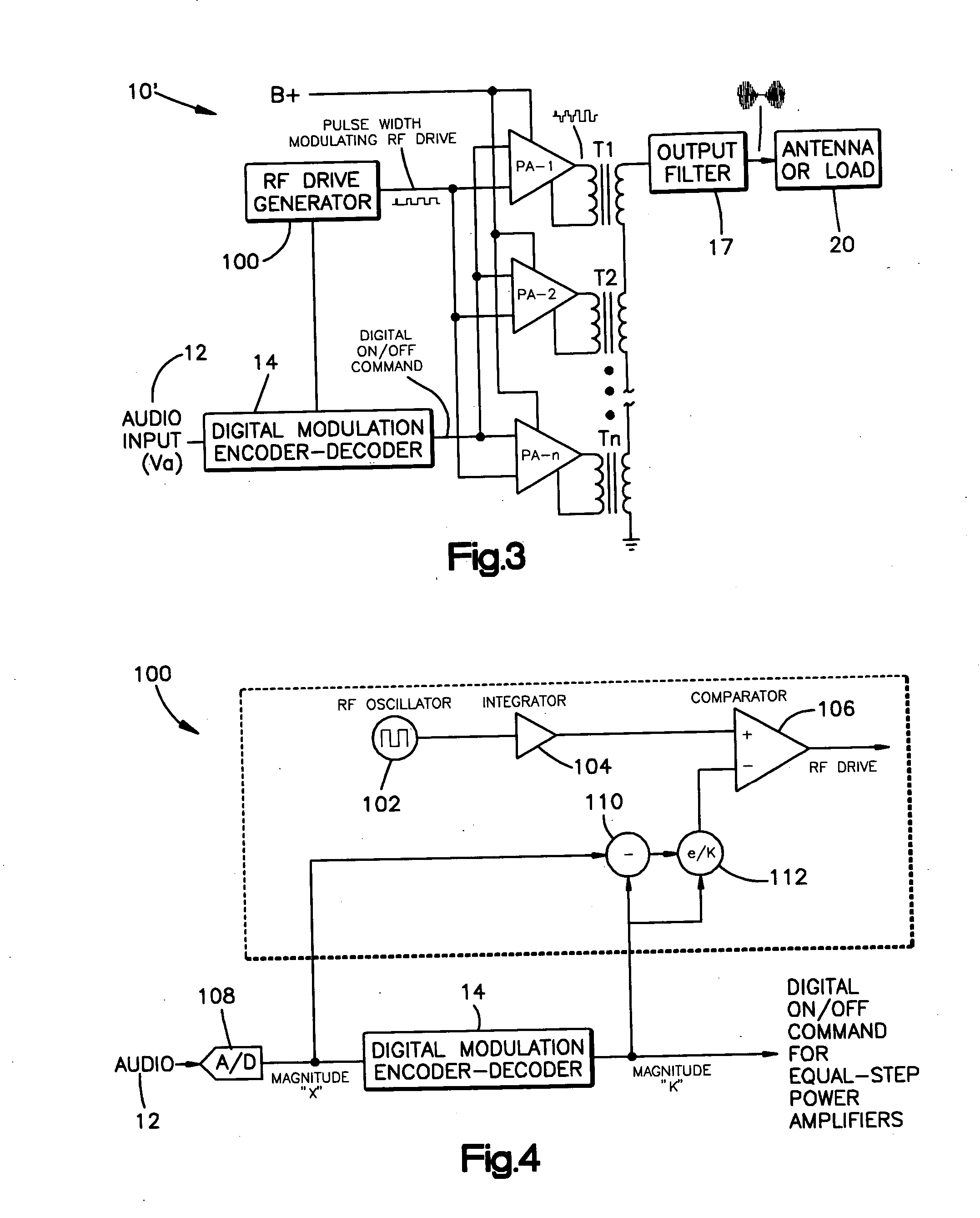
[0008] In accordance with a more limited aspect of the present invention, the pulse width is varied inversely with the magnitude of the applied audio signal.

Problems solved by technology

However, this technique has required lots of the same power amplifiers to achieve good resolution and, hence, cost may be significant.
This helps reduce the number of power amplifiers but the technique has many limitations because the power amplifiers are not exactly the same and, hence, there are variations in group delay, power gain, RF drive phase alignment with respect to each other.
This may create non-linearities which are difficult to correct.

Method used


Image

  • Digital amplitude modulation transmitter with pulse width modulating RF drive
  • Digital amplitude modulation transmitter with pulse width modulating RF drive
  • Digital amplitude modulation transmitter with pulse width modulating RF drive

Examples


Embodiment Construction

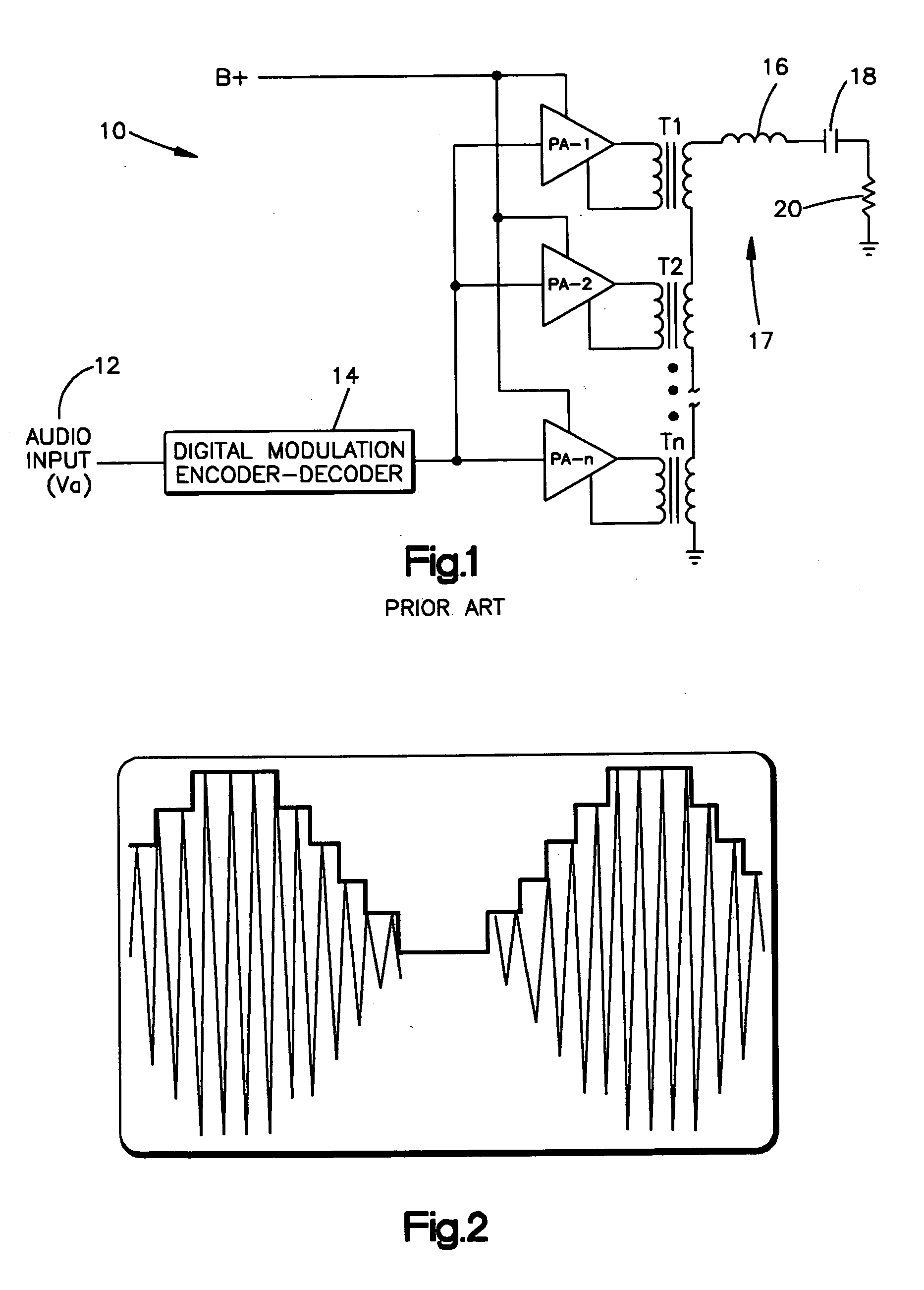
[0016] One application of the present invention is in conjunction with RF power amplifiers employed in an AM broadcast transmitter. An example of such a transmitter is presented in FIG. 1 and takes the form of a digital amplitude modulator such as that illustrated and described in the aforesaid U.S. Pat. No. 4,580,111.

[0017] The discussion that follows is directed to an explanation of the operation of the circuitry shown in FIG. 1 which serves as background for the discussion of the invention presented hereinafter.

[0018] Referring now to FIG. 1, the amplitude modulator 10 is illustrated as receiving an audio input signal 12 at a digital modulation encoder-decoder 14. This encoder-decoder 14 selects one or more of a plurality of power amplifiers PA-1 / PA-n to be turned on. These are equal amplitude amplifiers all of which when turned on serve to pass an RF signal (not shown) to the primary winding of one of a plurality of transformers T1 through Tn. The secondary windings of these t...


PUM


Abstract

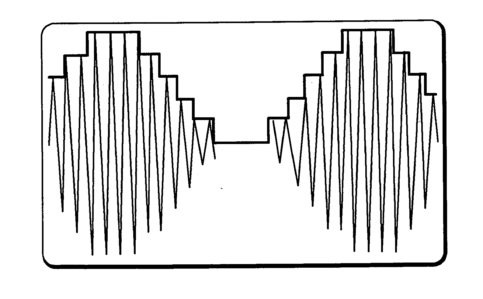
A digital amplitude modulation (AM) transmitter with pulse width modulating RF drive is presented. A plurality of RF amplifiers, each, when turned on, amplifies an applied RF drive signal by the same amount to provide a unit step RF output. An encoder supplies turn-on signals to turn on a number of the RF amplifiers wherein the number varies as a function of the value of an applied audio signal. The width of the unit step RF output is varied as a function of the number of the RF amplifiers that are turned on.

Description

BACKGROUND OF THE INVENTION [0001] This invention relates to the art of AM radio broadcasting and, more particularly, to an RF power amplifier system of the type employed in AM radio broadcasting and employing digital amplitude modulation with pulse width modulating RF drive. [0002] The patent to H. I. Swanson (U.S. Pat. No. 4,580,111) and the patent to K. T. Luu (U.S. Pat. No. 6,294,957) disclose an amplitude modulator for use in AM radio broadcasting and wherein the modulator serves to generate an amplitude modulated signal by selectively turning on and off a plurality of RF amplifiers in a digital manner to produce amplitude modulation. The amplifiers are essentially identical and each produces a signal of the same magnitude and duration known as a unit step or big step. The amplifiers are connected together in series so that big step signals are additive when combined and applied to a load, which may include a broadcasting antenna. [0003] A drive system supplies an RF signal whi...

Claims


Application Information

Patent Timeline
IPC IPC(8): H04B1/02H03C1/52
CPCH03C1/00H04B1/04H03C1/62H03C1/36H04L27/02H04L27/04
Inventor LUU, KY THOAI
Owner GATESAIR
Learn More