Wireless surveillance system

Inactive Publication Date: 2006-11-09
MURPHY GREG +1
View PDF4 Cites 55 Cited by
  • Summary
  • Abstract
  • Description
  • Claims
  • Application Information

AI Technical Summary

Benefits of technology

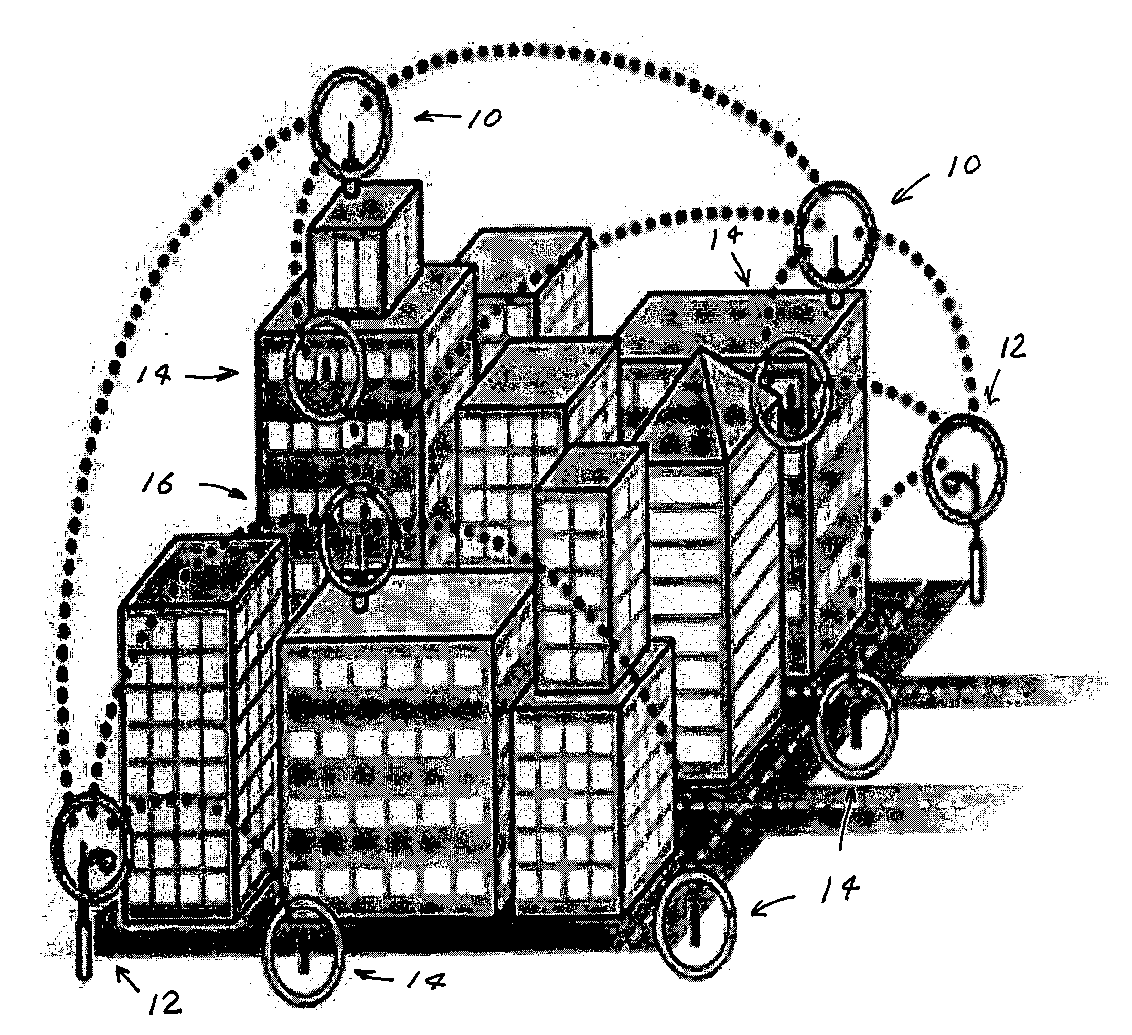
[0020] The present invention provides a surveillance system utilizing a mesh network having a large number of surveillance cameras. A plurality of limited range transceivers in direct or indirect communication with one or more of the cameras are located at a large number of nodes and are in communication with other transceivers in the network and are in communication with a control station. In a preferred embodiment most of the nodes are equipped with three transceivers to provide simultaneous communication with one or more camera and at the same time receive and transmit information from other nodes. This system utilizes a routing protocol that was initially developed for wireless voice-over Internet protocol services to large regions. This preferred system incorporates transceiver chips that enable co

Problems solved by technology

In order to limit interference among signals, however, transmitted power of WiFi systems is limited.
However, the construction of fiber optic trunk lines is expensive (sometimes very expensive) and the design and the construction of these lines can often take many months especially if the route is over private property or produces environmental controversy.
Often the expected revenue from the potential users of a particular trunk line under consideration does not justify the cost of the fiber optic trunk line.
In conjunction with the above availability requirements, weather-related attenuation limits the useful range of wireless data transmission at all wave

Method used


Image

  • Wireless surveillance system
  • Wireless surveillance system
  • Wireless surveillance system

Examples


Embodiment Construction

Wireless Mesh Network Surveillance System

[0024] A first preferred embodiment of the present invention provides a wireless video surveillance system that will allow Government agencies and security integrators to provide scalable city-wide infrastructures with an open platform for integration with their existing security and closed circuit television systems. One key element of the new system is based on a new mesh technology that provides multiple transceivers operating at various frequencies to allow for a highly scalable video infrastructure. Applicants have designed the system to maximize bandwidth, using multiple transceivers to enable deployment of wide-area and high-density surveillance systems. In addition, the system will enable automated threat detection as well as the security and redundancy advantages afforded by multiple-frequency systems incorporated into a mesh network architecture.

[0025] This preferred embodiment utilizes multiple transceivers (preferably three) at ...


PUM


Abstract

A surveillance system utilizing a mesh network having a large number of surveillance cameras. A plurality of limited range transceivers in direct or indirect communication with one or more of the cameras are located at a large number of nodes and are in communication with other transceivers in the network and are in communication with a control station. In a preferred embodiment most of the nodes are equipped with three transceivers to provide simultaneous communication with one or more camera and at the same time receive and transmit information from other nodes. This system utilizes a routing protocol that was initially developed for wireless voice-over Internet protocol services to large regions. This preferred system incorporates transceiver chips that enable communications over multiple frequencies and communications protocols. The signals from multiple frequencies are then converted into a digital format for routing to central command and control facilities, which can in turn communicate with mobile nodes. The use of multiple frequencies will enable simultaneous communication from multiple inputs without the bandwidth constraints of Wi-Fi systems that are designed for point-to-point Internet access. In addition, the use of a mesh network also enables redundancy to allow reliable communications even when one node or channel fails and enhanced security due to random channel allocation. The surveillance units may be mounted on light poles including street light poles. The also could be incorporated into light fixtures that are in turn mounted on the light poles.

Description

[0001] This application claims the benefit of Provisional Patent Applications, Ser. No. 60 / 666,084 filed Mar. 28, 2005 and Ser. No. 60 / 691,270 filed Jun. 15, 2005. The present invention relates to surveillance and security systems and in particular to wireless surveillance security systems.BACKGROUND OF THE INVENTION Need for Security [0002] Especially since Sep. 9, 2001 security has become big business in the United States and in most countries of the world. People and governments are concerned with the protection of locations that are terrorist targets. These include stadiums, government installations and military installations. Most terrorist targets are equipped with perimeter outdoor lighting. Local Wireless Radio Communication [0003] Local wireless communication services represent a very rapidly growing industry. Wireless communication equipment in the Unites States includes equipment known as “Wireless Fidelity” equipment (also called “WiFi” or “Wireless Networking”). This eq...

Claims


Application Information

Patent Timeline
IPC IPC(8): H04N7/173
CPCG08B13/19645G08B25/10G08B13/1966
Inventor MURPHY, GREGHAMALIAN, KNIGHT
Owner MURPHY GREG
Why Eureka
Try Eureka