Dose counting in metered dose inhaler

a technology of metered dose and inhaler, which is applied in the direction of respirator, respirator testing, signalling system, etc., can solve the problems of increasing the cost of treatment of an illness, user facing the possibility of running out of necessary medication, and confusing traditional mdi inhaler devices

Inactive Publication Date: 2006-11-16
GENOVA PERRY +2
View PDF12 Cites 92 Cited by
  • Summary
  • Abstract
  • Description
  • Claims
  • Application Information

AI Technical Summary

Problems solved by technology

Traditional MDI inhaler devices are known to be confusing to the user with respect to the number of medication containing actuations remaining in the canister at any one time.
Accordingly, the user is faced with the possibility of running out of necessary medication at a critical time.
Further, the disposal of a canister of medication when there are still a number of doses remaining can lead to increased expense in the treatment of an ailment.
Still further complications with the traditional inhalers mean that a user is forced to manually determine the timing between dosing.
When coupled with the irregularity of the dosing schedules improper dosing of a patient becomes a genuine concern.

Method used


Image

  • Dose counting in metered dose inhaler
  • Dose counting in metered dose inhaler
  • Dose counting in metered dose inhaler

Examples


first embodiment

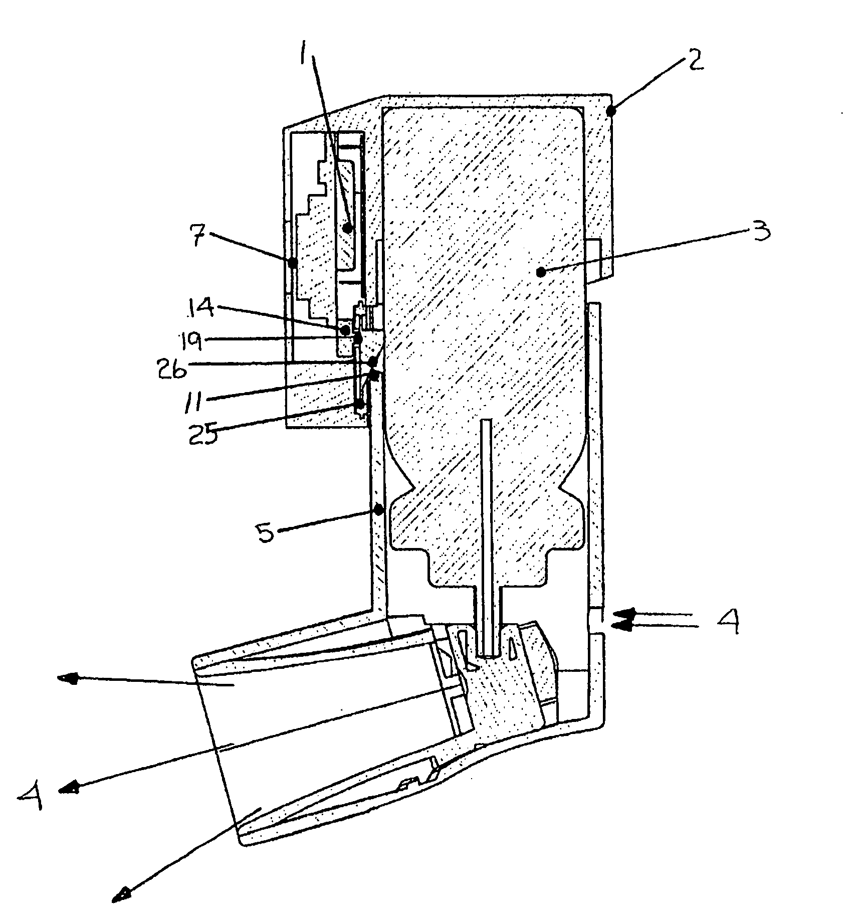
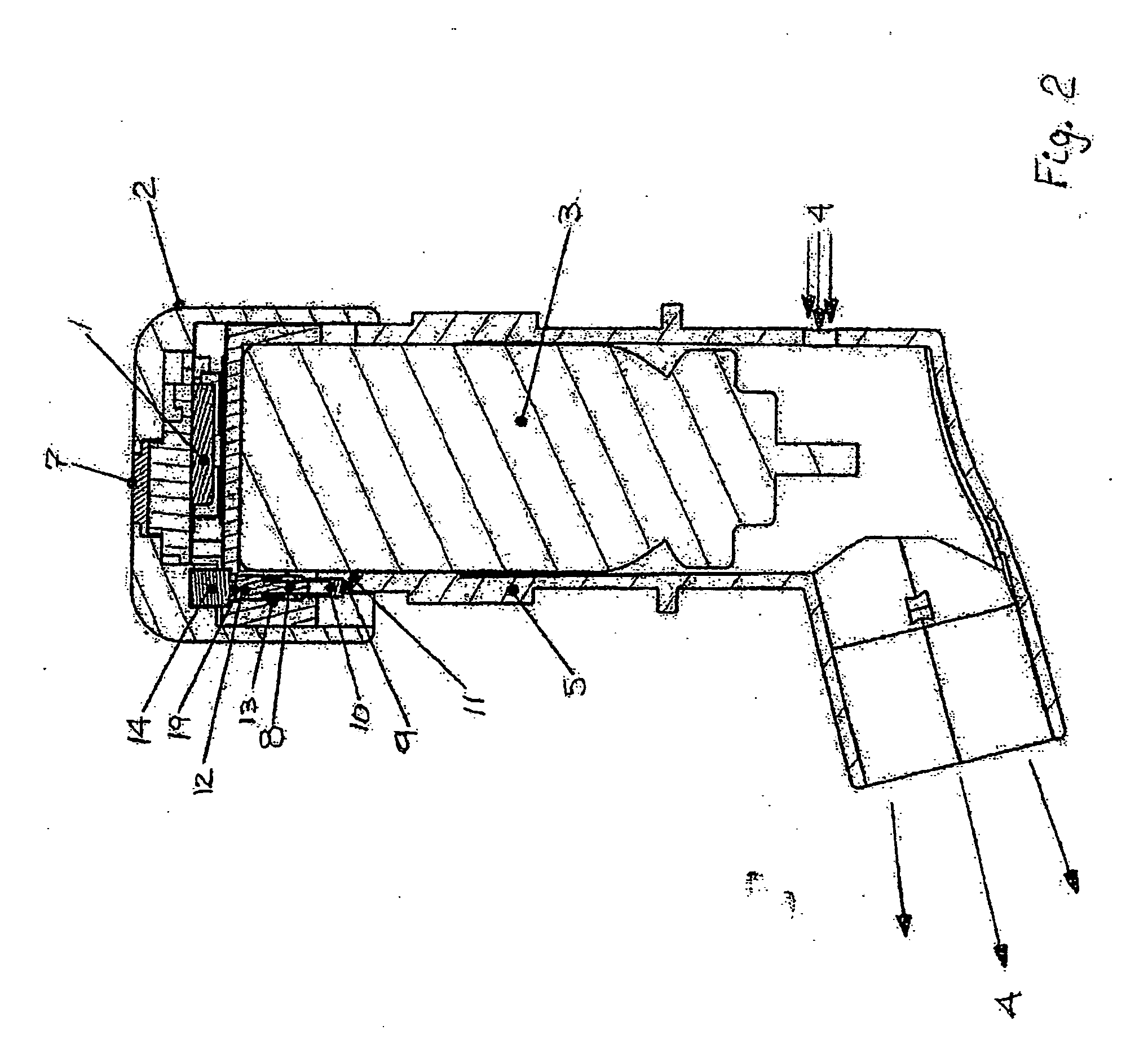
[0031] Referring now to FIG. 2, there is shown a plan view of a pMDI in accordance with the invention. In the FIG. 2 embodiment, the LCD 7 is located on top of EDC module 1, and a trigger assembly 8 is mounted at a peripheral edge of cap 2. The trigger assembly is made up of a first plunger 10 in communication with an upper edge 11 of actuator body 5. A second plunger 12 is positioned about the proximal end of a spring 13 that is fitted between the first and second plungers. The second plunger is positioned to contact button 19 of switch 14 on EDC 1 circuit board. As a user urges the canister assembly down into the actuator body, upper edge 11 of the actuator body forces plunger 10 to compress spring 13 which, in turn, causes plunger 12 to contact button 19 to close switch 14. The closing of switch 14 causes the dose count to be updated. The updated dose count is displayed on LCD 7. Thus, update of the display count occurs at a predetermined point in the travel of canister 3 within ...

second embodiment

[0032]FIG. 3 is a plan view of a pMDI in accordance with the invention. As in the FIG. 2 embodiment, the LCD is positioned at the top of the cap. The attachment of the cap to the canister is also the same as described in connection with the FIG. 2 embodiment. However, the switching mechanism in FIG. 3 differs from that of FIG. 2. In FIG. 3, count actuation is achieved through a horizontally mounted flip-up style switch 14 (e.g. PANASONIC P11152STR). When the canister is depressed relative to the actuator, switch 14 is closed to register a count, as upper edge 11 of the actuator deflects an integral, spring-biased, position-sensing arm 15 on switch 14. Over travel is accommodated within the switch mechanism itself.

third embodiment

[0033]FIG. 4 is a plan view of a pMDI in accordance with the invention. As in the FIG. 2 and FIG. 3 embodiments, the LCD is positioned at the top of the cap. Also the attachment of the cap to the canister is the same as described in connection with the FIGS. 2 and 3 embodiments. However, in the FIG. 4 embodiment, switching is achieved through a switch 16 that is mounted at an edge 17 of an EDC 1 circuit board. Orientation is such that the direction of actuation of switch 16 is parallel to the plane of the circuit board of EDC 1. A boss, or rib, 18 on the inside of upper edge 11 of actuator 5 slides against switch 16 depressing contact button 19 to initiate a count. Actuator 5 with rib 18 can then travel past the closure position of switch 16 by an amount sufficient to accommodate over travel without causing a false count by again actuating switch 16 on return travel.


PUM


Abstract

A counter for indicating the number of doses left in a canister that is suitable for use in a metered dose inhaler. The counter is affixed to the canister and includes a module for providing an indication of the number of doses left in the canister and a triggering mechanism for updating the indication in response to activation of the inhaler.

Description

FIELD OF THE INVENTION [0001] The present invention relates to electronic monitoring and counting of medication dosages, and in particular to a metered dose inhaler that includes an electronic counter module. BACKGROUND OF THE INVENTION [0002] Metered dose inhalers (“MDI”) of various configurations are known for dispensing medication into the mouth or nasal passages of a patient. Medication is expelled from the actuator and inhaled by the patient and absorbed by the mouth, nose, throat and lungs. One example is the device commonly used by asthma sufferers for dispensation of airway opening drugs. These are often called “Press & Breathe” inhalers and require simple pressing on the canister and inhalation by the user. [0003] A pressurized metered dose inhaler (“pMDI”) is designed to deliver therapeutic agents, e.g. medicaments, to the human respiratory tract or nasal cavity. Accordingly, the pMDI contains the active substance, dissolved or suspended, in a fluid propellant system that ...

Claims


Application Information

Patent Timeline
Patent Type & Authority Applications(United States)
IPC IPC(8): A61M11/00G08B3/00A62B27/00
CPCA61M15/0065A61M15/008A61M2205/52A61M15/009A61M15/00A61J7/02
Inventor GENOVA, PERRYDEATON, DANKHARE, MATT
Owner GENOVA PERRY
Why Eureka
Try Eureka