Wheel supporter with a brake

a technology of brakes and supporters, applied in the direction of castors, mechanical devices, transportation and packaging, etc., can solve the problems of high cost of castors with brake mechanisms, and achieve the effect of simplifying assembly processes and reducing costs

Inactive Publication Date: 2006-11-16
YAN LI LAN
View PDF7 Cites 16 Cited by
  • Summary
  • Abstract
  • Description
  • Claims
  • Application Information

AI Technical Summary

Benefits of technology

[0005] One purpose of the invention is to offer a wheel supporter with a brake quickly combined with the wheel supporter, simplifying assembling processes, reducing its cost, and applicable to various types of wheel supporters for small wheels.

Problems solved by technology

So this castor with a brake mechanism may cost high, involving many processes in assembling.

Method used


Image

  • Wheel supporter with a brake
  • Wheel supporter with a brake
  • Wheel supporter with a brake

Examples


Embodiment Construction

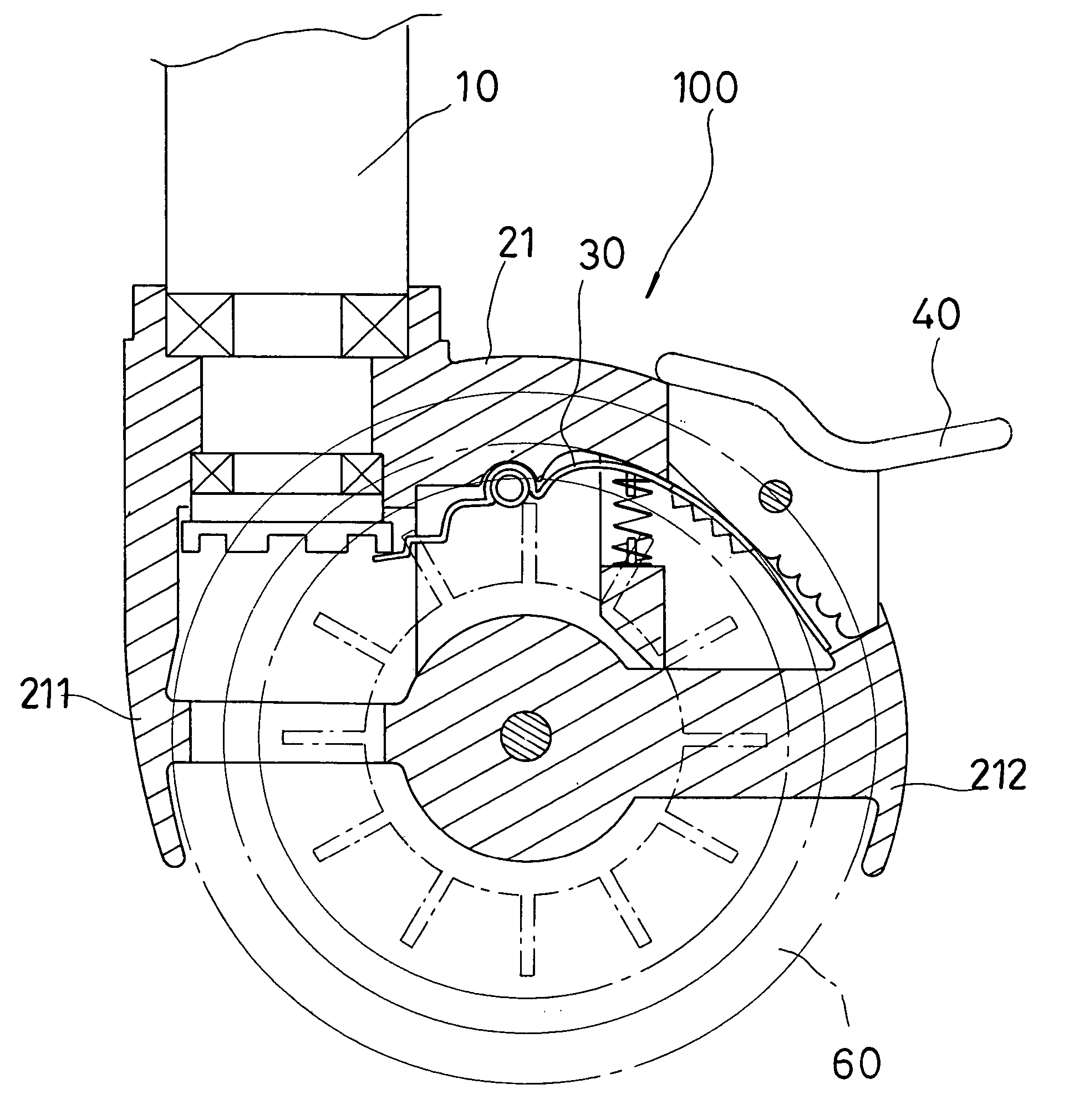
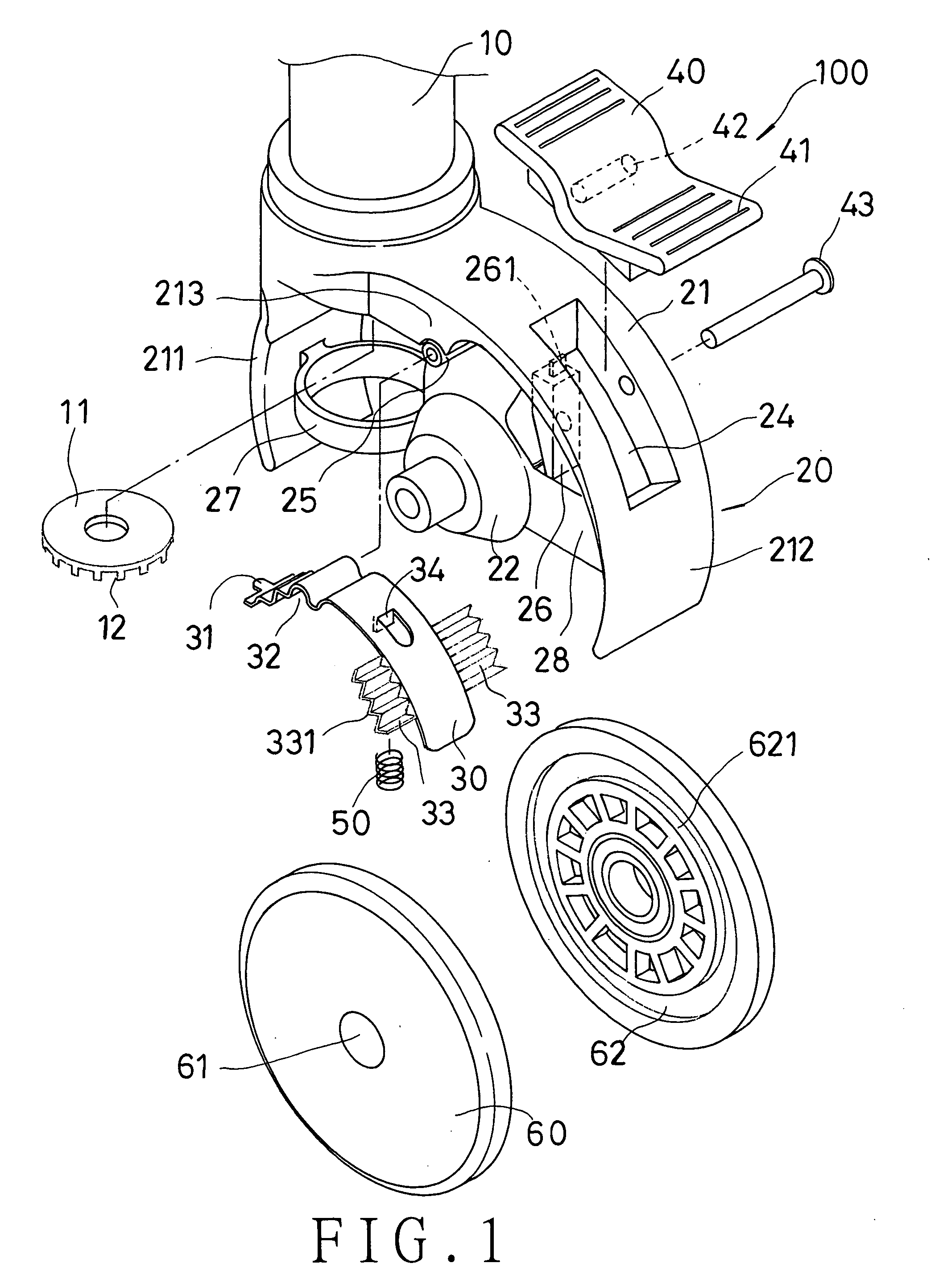
[0019] A preferred embodiment of a wheel supporter with a brake in the present invention, as shown in FIGS. 1 to 4, includes a rotary shaft 10, a base 20, a brake plate 30, a pedal 40, and a return spring 50.

[0020] The rotary shaft 10 is composed of a shaft body extending from a vehicle, and a disc gear 11 fixed around the lower end of the shaft body and having a plurality of teeth 12 spaced apart equidistantly to form a plurality of gaps and extending downward from its outer circumference. But the teeth 12 can be arranged in other ways.

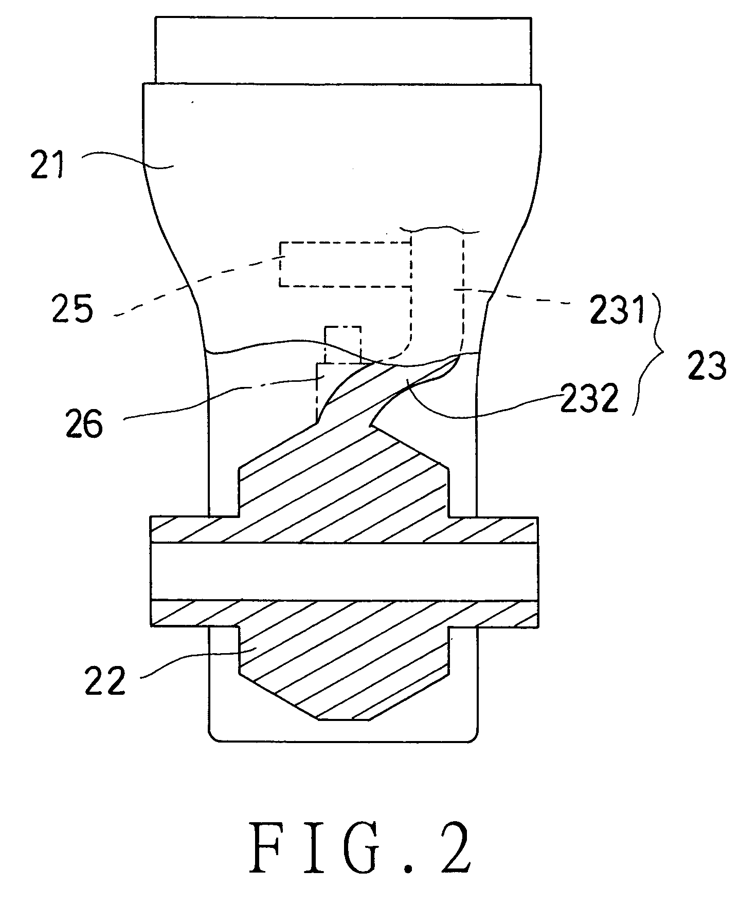
[0021] The base 20 is connected with the rotary shaft 10 functioning as a pivot, composed of a covering member 21, a shaft support member 22, and an eccentric supporting member 23 located between the covering member 21 and the shaft supporting member 22. The covering member 21 has its upper portion pivotally connected with the rotary wheel 10, and a long hole 24 formed in a rear portion. The eccentric support member 23 consists of an upper stage 23...


PUM


Abstract

A wheel supporter with a brake includes a rotary shaft, a base, a pedal, a brake plate and a return spring. The base has a covering member, a shaft support member, and an eccentric support member. The eccentric support member has an upper stage provided with a sidewise round post, and the brake plate has a front projection, two wings provided in a rear portion, and an upper recess formed to mount on the round post. If the pedal is stepped down, the brake plate is pressed down to force the wings contact the wheel to produce frictional resistance against the wheel, and at the same time the front projection of the brake plate fits in one of the gaps formed by every two teeth of a disc gear fixed with a lower end of the rotary shaft to stop the rotary shaft immovable. The brake plate is easily combined with the wheel supporter, and applicable to various types of wheels.

Description

BACKGROUND OF THE INVENTION [0001] 1. Field of the Invention [0002] This invention relates to a wheel supporter with a brake, particularly to one provided with a pedal stepped to let a brake plate to swing like a seesaw and possible to stop a wheel and the wheel supporter at the same time, and the brake plate formed integral possible to be combined with the wheel supporter quickly, and applicable to various types of wheel supporters. [0003] 2. Description of the Prior Art [0004] A wheel supporter used for a small diameter wheel are often combined with a brake for braking and stopping the wheel, especially a rotary wheel is structured to rotate and turn around, and the brake stops the wheel both from rotating and from turning around at the same time or separately. Further, a U.S. Pat. No. 4,941,552, “Castor with brake mechanism” applied on Oct. 7, 1988, discloses a wheel supporter for a motorcycle, which has a brake fixed to mount on the wheel supporter, which cannot be combined quic...

Claims


Application Information

Patent Timeline
Patent Type & Authority Applications(United States)
IPC IPC(8): F16D55/04F16D65/00
CPCB60B33/0021B60B33/0028B60B33/0042B60B33/0049B60B33/0057F16D49/00B60B33/0073B60B33/0086B60B33/021B60B33/025B60B33/0068
Inventor YAN, LI-LAN
Owner YAN LI LAN
Why Eureka
Try Eureka