
Rechargeable battery

a rechargeable battery technology, applied in the field of rechargeable batteries, can solve the problems of deteriorating welds, difficult to securely weld electrolyte sealing members onto the cap plate, and poor irradiation of lasers used for welding, so as to improve the structure of the electrolyte injection opening and improve the sealing structur

Active Publication Date: 2006-11-16
SAMSUNG SDI CO LTD
View PDF3 Cites 31 Cited by
  • Summary
  • Abstract
  • Description
  • Claims
  • Application Information

AI Technical Summary

Benefits of technology

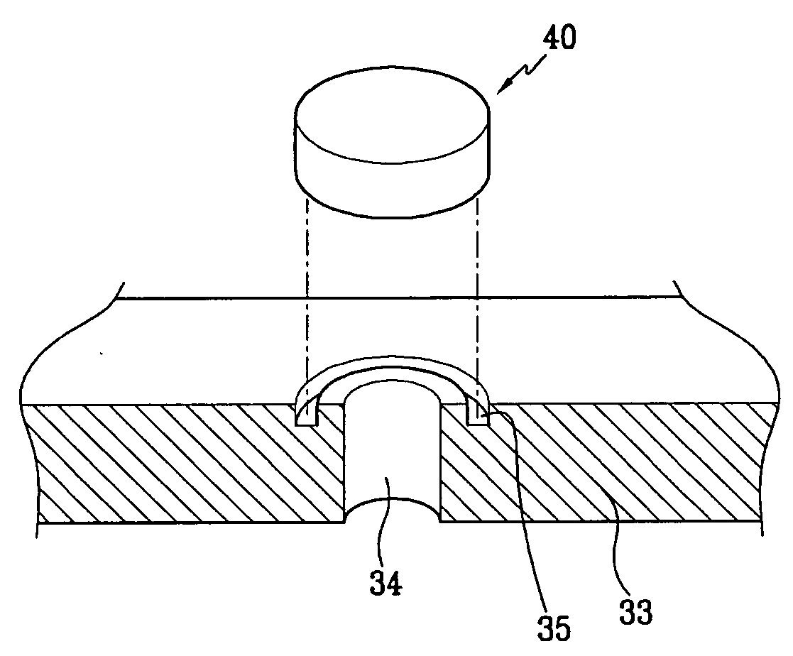
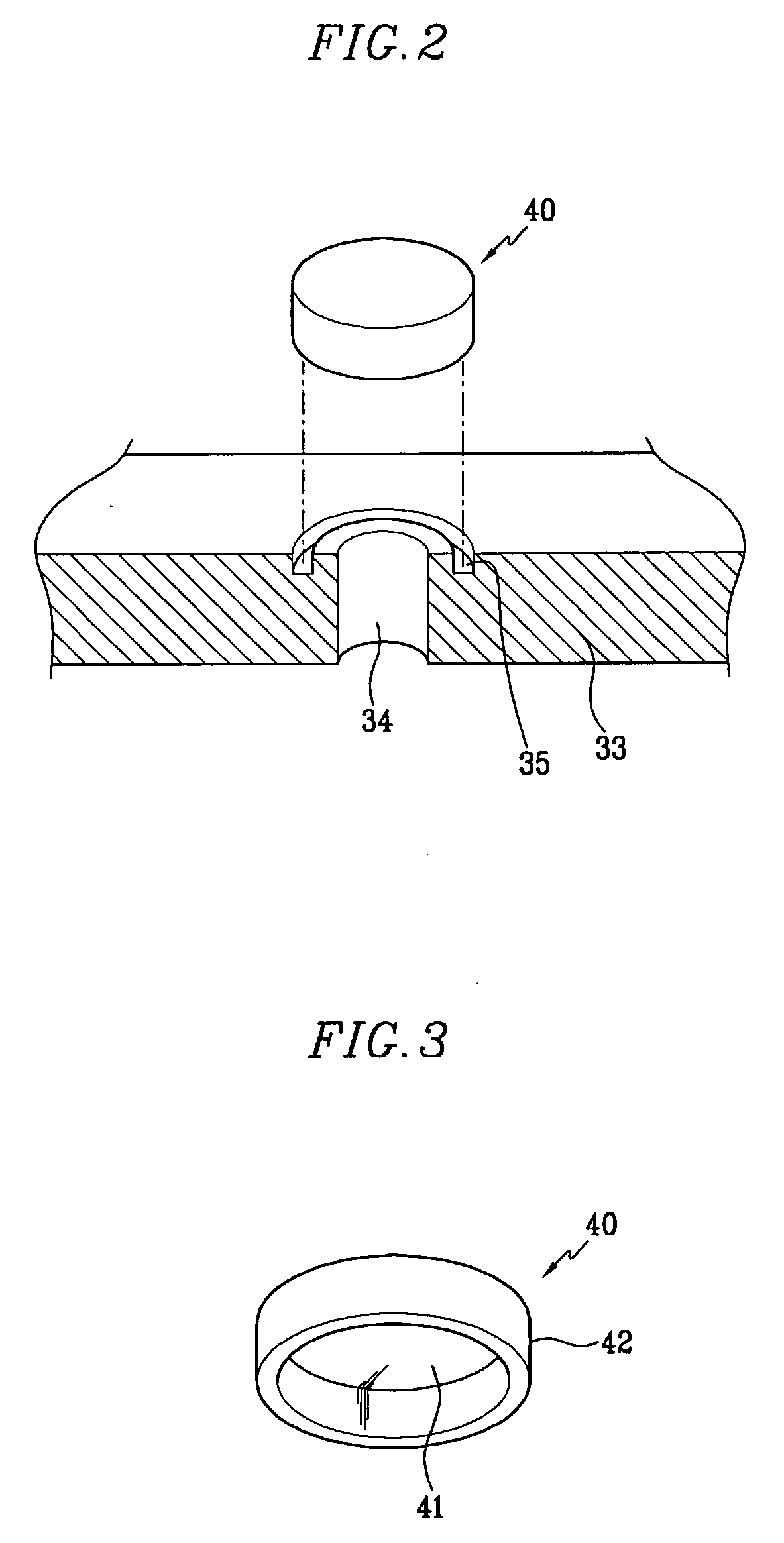
The present invention provides a rechargeable battery with an improved sealing structure for the electrolyte injection opening by improving the structure of the electrolyte injection opening and an electrolyte sealing member for closing the electrolyte injection opening. The electrolyte sealing member is engaged with a groove formed along a periphery of the electrolyte injection opening. The electrolyte sealing member is welded to the cap assembly or the case to seal the case. The electrolyte injection opening may be formed to have a circular cross section. The groove may be formed to contact the electrolyte injection opening. The electrolyte sealing member may be press-fit into the groove or engaged with the groove and fixed onto the case or the cap assembly by welding. The electrolyte sealing member may have a slant face or a vent to release pressure at a predetermined level. The rechargeable battery may be used for driving a motor.

Problems solved by technology

However, when the spherical electrolyte sealing member seals the electrolyte injection opening, as used in conventional rechargeable batteries, it is difficult to securely weld the electrolyte sealing member onto the cap plate because the upper surface of the electrolyte sealing member may not form an exact circle.
Thus, a laser used for welding is not well irradiated onto the junction face.
Further, when the electrolyte sealing member is inserted into the electrolyte injection opening and welded thereto, a portion between the electrolyte injection opening and the electrolyte sealing member may be smeared with electrolyte solution, thus deteriorating the weld.
Poor welding may allow the electrolyte solution to leak out along the electrolyte injection opening causing a short-circuit.

Method used


Image

  • Rechargeable battery
  • Rechargeable battery
  • Rechargeable battery

Examples


Embodiment Construction

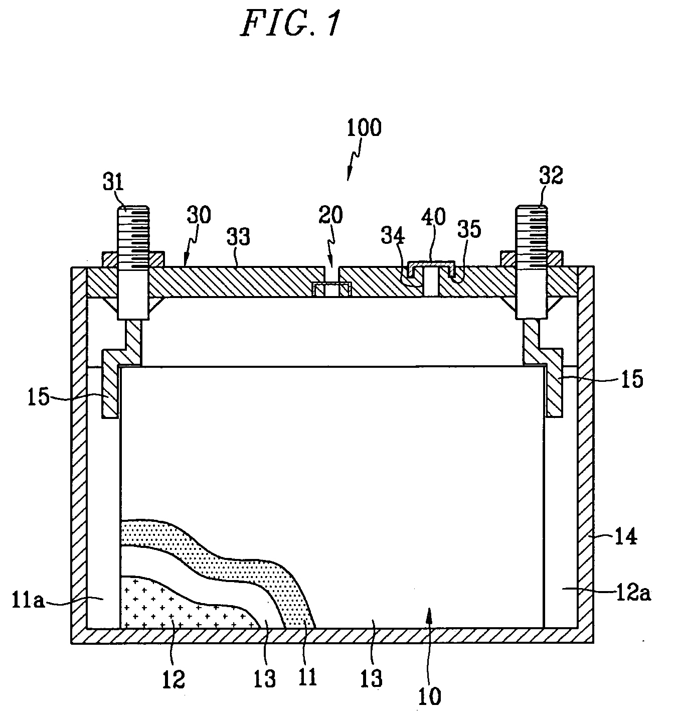
[0038] Referring to FIG. 1, a rechargeable battery 100 includes an electrode assembly 10 having a positive electrode 11 and a negative electrode 12 with a separator 13 interposed between them, a prismatic case 14 for housing the electrode assembly 10, a cap assembly 30 mounted on an opening of the case 14 and sealing the case 14, and a positive terminal 31 and a negative terminal 32 which are electrically connected to the positive electrode 11 and the negative electrode 12, respectively, through tabs 15. The positive and negative electrode taps protrude to the outside of the cap assembly 30.

[0039] The cap assembly 30 includes a safety vent 20 for exhausting gas generated by the rechargeable battery 100, an electrolyte injection opening 34 through which electrolyte solution is injected into the case 14, and an electrolyte sealing member 40 for sealing the electrolyte injection opening 34 to seal the case 14. The electrolyte injection opening 34 may be formed at one side of the cap a...


PUM

PropertyMeasurementUnit
distanceaaaaaaaaaa
circumferenceaaaaaaaaaa
diameteraaaaaaaaaa

Abstract

A rechargeable battery having an electrolyte sealing member covering and sealing the electrolyte injection opening. An electrode assembly includes a positive electrode, a negative electrode and a separator wound in a jelly roll configuration. A case houses the electrode assembly. A cap assembly is combined with the case to seal the case, the cap assembly including a positive terminal connected to the positive electrode and a negative terminal connected to the negative electrode. An electrolyte injection opening is formed on the case or the cap assembly. A groove is formed along a periphery of the electrolyte injection opening. An electrolyte sealing member engages the groove.

Description

CROSS-REFERENCE TO RELATED APPLICATION [0001] This application claims priority to and the benefit of Korean Patent Application No. 10-2005-0040590 filed in the Korean Intellectual Property Office on May 16, 2005, the entire content of which is incorporated herein by reference. BACKGROUND OF THE INVENTION [0002] 1. Field of the Invention [0003] The present invention relates to a rechargeable battery. More particularly, the present invention relates to a rechargeable battery with an improved sealing structure of an electrolyte injection opening. [0004] 2. Description of the Related Art [0005] Distinct from a primary battery, a secondary (rechargeable) battery can be repeatedly charged and discharged. Recently, researchers are developing high-power rechargeable batteries using non-aqueous electrolyte which has a high energy density. [0006] Low-capacity batteries having a single battery pack are used as a power source for various portable electronic devices such as mobile phones and lap...

Claims


Application Information

Patent Timeline
Patent Type & Authority Applications(United States)
IPC IPC(8): H01M2/08H01M2/36H01M2/04H01M50/627H01M50/636
CPCH01M2/0486H01M2/1241H01M10/04H01M2/365H01M2/368H01M2/361Y02E60/10H01M50/3425H01M50/636Y02P70/50H01M50/627H01M50/183H01M50/60H01M50/20H01M10/0431H01M2220/20
Inventor KIM, YONG-SAMKIM, KI-HOLIM, HONG-SUPLEE
Owner SAMSUNG SDI CO LTD
Learn More