Catheter, catheter device and imaging diagnostic apparatus

a catheter and imaging diagnostic technology, applied in the field of catheters, can solve the problems of difficult to achieve the necessary precision of the radiation source, and the failure of known apparatuses to treat patients

Inactive Publication Date: 2006-11-16
SIEMENS AG
View PDF14 Cites 137 Cited by
  • Summary
  • Abstract
  • Description
  • Claims
  • Application Information

AI Technical Summary

Benefits of technology

[0035] According to a further embodiment, a device is provided for generating an external magnetic field of predetermined direction and strength for the purpose of deflecting the deflection means. With the proposed device, the imaging diagnostic apparatus is expanded by the further function of a precise guidance of the catheter in the vascular system. For this purpose the deflection means provided in the area of the free end of the catheter can be selectively deflected using directed external magnetic fields and in this way a change in direction of the free end of the catheter to a predetermined direction can be achieved.
[0036] In particular in the field of angiography it has proven advantageous to combine the proposed imaging diagnostic apparatus with what is referred to as a “bi-plane x-ray apparatus”, in which at least one x-ray source, a first semiconductor detector arranged in a first plane and a second semiconductor detector arranged in a second plane different from the first plane are provided. This enables large-area survey exposures to be produced on which the position of the catheter in the vascular system can be recognized, in particular on the basis of the x-ray markers provided thereon.

Problems solved by technology

In practice the problem when using the known catheter is that the radiation source often cannot be positioned with the necessary precision therewith in the vessel that is to be treated.
Nonetheless, it has once again proven difficult in practice, after producing such a three-dimensional representation of the vessel, to arrange a radiation source precisely at a therapy position that is recognizable on the three-dimensional representation.
That said, however, the known apparatuses permit no treatment, more particularly of restenoses.

Method used


Image

  • Catheter, catheter device and imaging diagnostic apparatus
  • Catheter, catheter device and imaging diagnostic apparatus
  • Catheter, catheter device and imaging diagnostic apparatus

Examples


Embodiment Construction

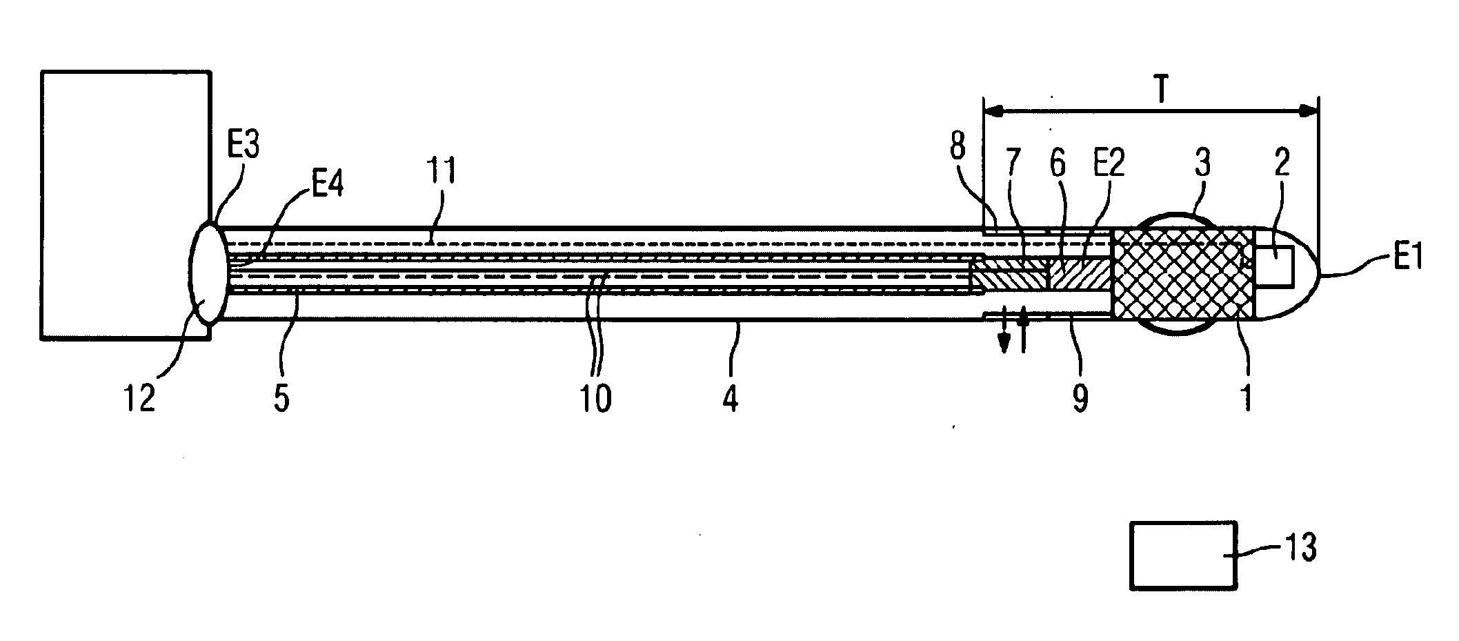
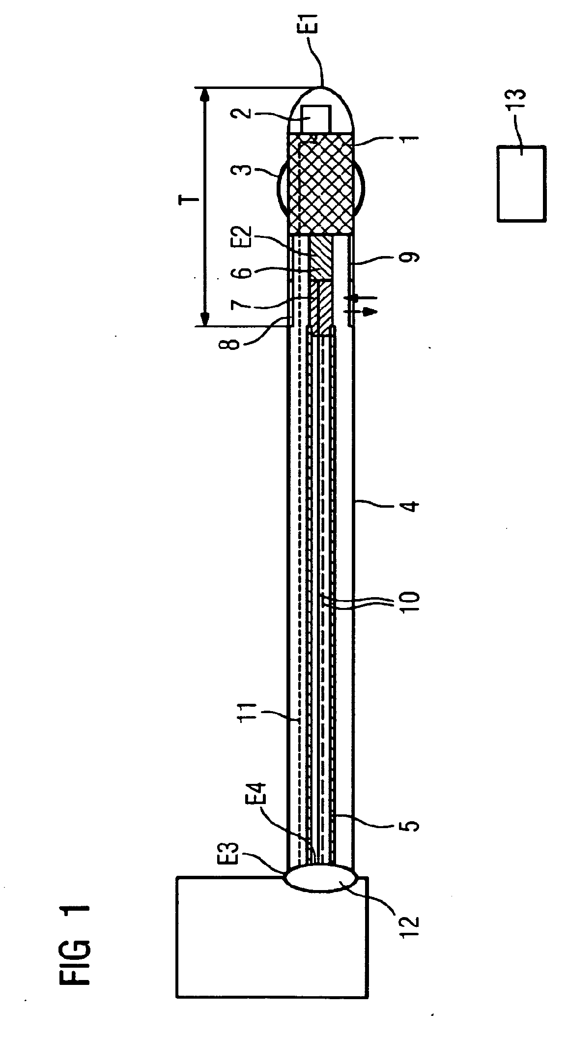
[0046] In the catheter shown in FIG. 1, a free end E1 is embodied as a rounded shape. In the area of the free end E1 the catheter is provided with a radiation source 1 by means of which β or γ radiation can be generated for therapeutic purposes.

[0047] Position indicating means are designated by the reference numeral 2. Said means can be, for example, three coils which are arranged offset by 90° to one another in the X, Y and Z direction. However, the coils can also be arranged relative to one another under a different offset angle, for example 60°. Instead of the coils, other suitable transmitting or receiving means, permanent magnets for example, can also be provided in an appropriate offset arrangement with regard to the direction of the magnetic flux. The reference numeral 3 denotes an inflatable balloon.

[0048] Accommodated in a tube 4 of the catheter is a core 5 which is rotatable about a catheter axis and at the first end E2 of which an ultrasound transducer 6 and a transmitt...


PUM


Abstract

The invention relates to a catheter for brachytherapy having a radiation source for generating β or γ rays. In order to be able to position the catheter as accurately as possible it is proposed according to the invention that a position indicating means is provided in the area of a free end of the catheter, by means of which position indicating means a position in a three-dimensional coordinate system can be determined on the basis of interactions produced when an external magnetic field is applied.

Description

CROSS REFERENCE TO RELATED APPLICATIONS [0001] This application claims priority of German application No. 102005022120.3 filed May 12, 2005, which is incorporated by reference herein in its entirety. FIELD OF THE INVENTION [0002] The invention relates to a catheter. It further relates to a catheter device as well as to an imaging diagnostic apparatus comprising the catheter or the catheter device. BACKGROUND OF THE INVENTION [0003] A catheter of this type is known from WO 97 / 25102 A1. In practice the problem when using the known catheter is that the radiation source often cannot be positioned with the necessary precision therewith in the vessel that is to be treated. [0004] In order to counteract this disadvantage, the known catheter has been combined with imaging apparatuses. These can be, for example, apparatuses in which the image is generated on the basis of ultrasound signals. An apparatus of this type is known for example from DE 198 27 460 A1. [0005] WO 01 / 11409 A2 describes ...

Claims


Application Information

Patent Timeline
Patent Type & Authority Applications(United States)
IPC IPC(8): A61N5/00
CPCA61B5/0066A61B5/0084A61B5/06A61B5/062A61B5/721A61B8/12A61N5/1049A61B2019/5278A61B2019/5454A61M25/0082A61M25/10A61N5/1002A61B19/54A61B90/39A61B2090/3782A61B2090/3954
Inventor MASCHKE, MICHAEL
Owner SIEMENS AG
Why Eureka
Try Eureka