Echogenic medical device

a biomedical device and echogenic technology, applied in the field of echogenic biomedical devices, can solve the problem of difficult visualization of placement, and achieve the effect of not easy to visualiz

Inactive Publication Date: 2005-03-03
COWLES VENTURES LLC
View PDF83 Cites 40 Cited by
  • Summary
  • Abstract
  • Description
  • Claims
  • Application Information

AI Technical Summary

Benefits of technology

[0011] This invention relates to echogenic biomedical devices and methods of preparing them. More particularly, to brachytherapy sources where it is imperative to determine the exact placement of the device within the body at the time of treatment and the placement is not easily visualized. One or all of the following techniques can monitor the post implant position: ultr

Problems solved by technology

More particularly, to brachytherapy sources where it is imperative to determine the exact placement

Method used


Image

  • Echogenic medical device
  • Echogenic medical device
  • Echogenic medical device

Examples


example 1

Echogenic Devices

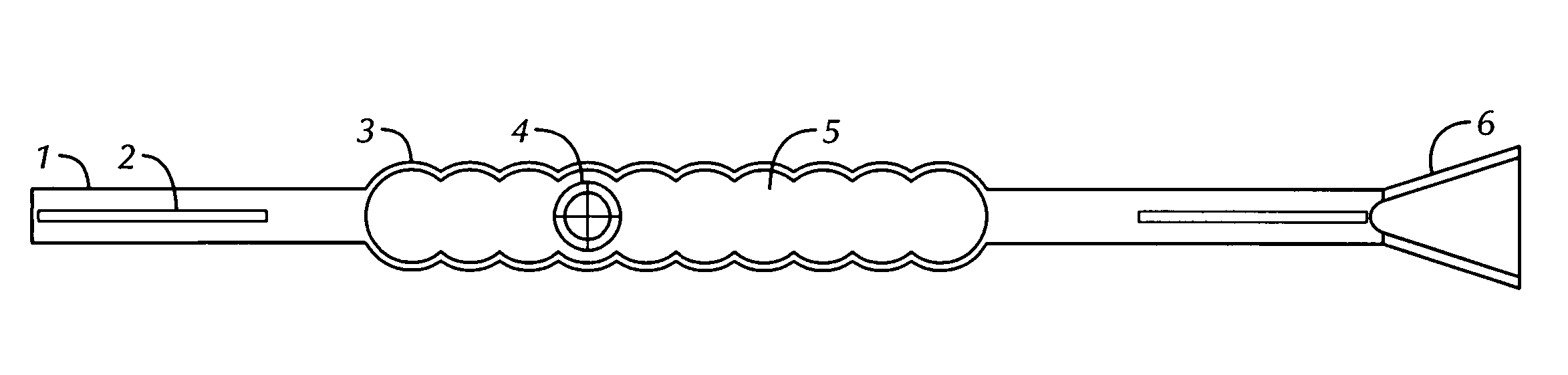
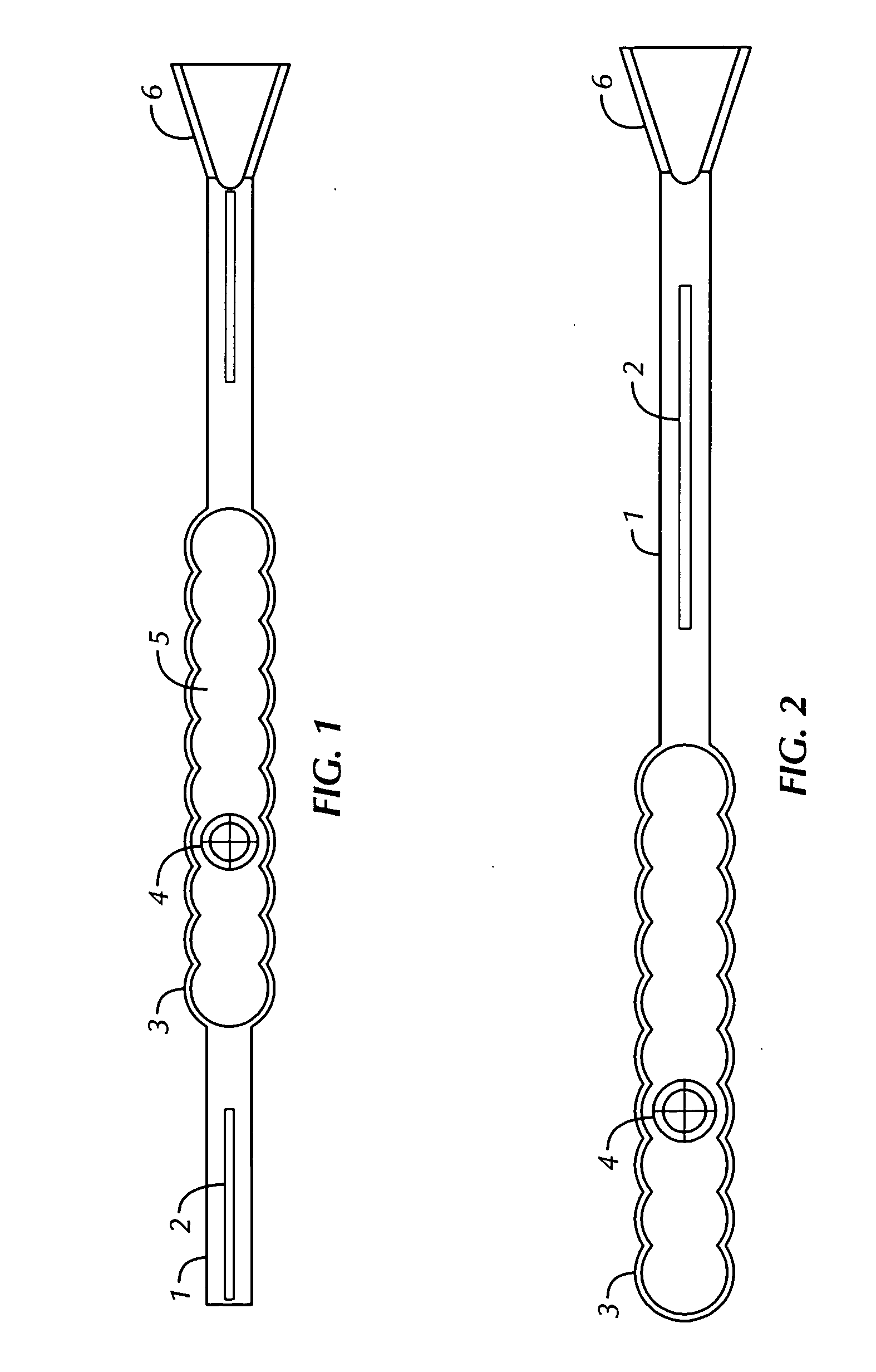
[0090]FIGS. 1-3, and 5-7 show echogenic devices which comprise one or more ribbed surface (i.e., having hemispherical repeat units) and a hollow gas-filled chamber, one or more spacer elements, and optionally an incorporated spacer-docking guide. Shown in FIG. 1 is one embodiment of the present invention having a single body chamber 5 with a parabolic echogenic surface 3 defining the gas-filled chamber 5. Two spacer elements 1, are found on either side of the body chamber, each of which have a radiographic and / or NMR high-density material 2 in the spacer element. A spacer-docking guide 6 is found at the end of the device.

[0091] In FIGS. 1-3, and 7, a hollow air filled chamber 5 enclosed by semi-circular exterior polymeric material 3 hermetically sealing the radioactive source 4 which providing a ultrasonic deflecting surface and high differential gradient to the tissue which the device is implanted. The device is constructed with solid or hollow rods 1 on one or b...

example 2

Manufacturing Process

[0095] One configuration of the current invention may be manufactured by first cutting to length 10 mm of extruded liquid crystal polymer (LCP) tubing 0.8 mm O.D. with a 0.1 mm wall. Insert into one end a solid rod of LCP 0.4 mm O.D. by 2.75 mm in length containing a central silver wire 0.1 mm O.D. and ultrasonically welding the tubing to the solid rod. A 0.5 mm resin sphere containing one mCi (37 MBq) of Iodine-125 is placed into the open end of the LCP tubing. A second solid rod of LCP 0.4 mm O.D. by 2.75 mm in length containing a central silver wire 0.1 mm O.D. is inserted into the open end of the tubing and the rod ultrasonically welding to the tubing. The final configuration may be used as constructed or further modified by shaping the open hermetically sealed central section into hemispherical repeating units by ultrasonically heating the material and forming FIG. 5.

[0096] Another configuration of the current invention may be manufactured by first cuttin...

example 3

Manufacturing the Hemispherical Repeating Units

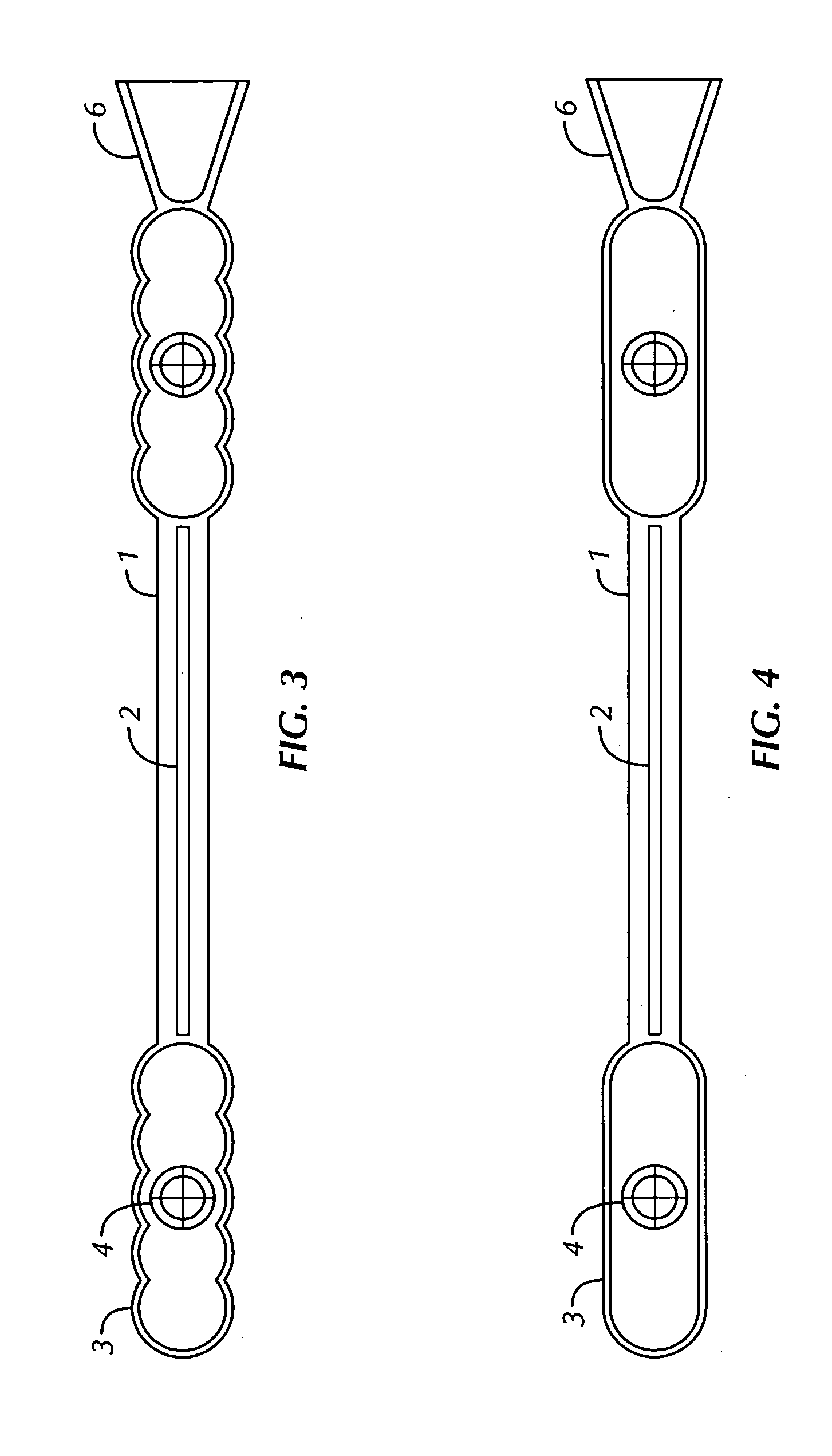
[0098] The echogenic surface of the device may comprise the surface of the extruded LPC tubing, as shown in FIG. 4, or it may be further modified by shaping the open hermetically sealed central section into hemispherical repeating units by ultrasonically heating the material as depicted in FIGS. 1-3 and 5-7. The hemispherical repeating units may be formed into the stock LCP prior to construction or at any point in the process including at the point of welding the first or second LCP rods.


PUM


Abstract

Echogenic medical devices, methods of fabrication and methods of use are disclosed. The device can be adapted to be inserted into a patient. The echogenic construction can be incorporated into the device at the time of fabrication providing acoustic impedance different from that of the surrounding biological tissue or fluid. The medical device is designed for use with an ultrasound imaging system to provide real-time location of the insertion and guidance at the time the device is implanted in a patient, such as in brachytherapy. Following placement of the device the position can be evaluated over time to insure the device remains in proper alignment and functional. Furthermore, the device is designed to incorporate a spacer element at one or both ends to provide separation between radioactive elements.

Description

BACKGROUND OF THE INVENTION [0001] I. Field of the Invention [0002] The present invention relates generally to the fields of echogenic biomedical devices. More particularly, it provides a brachytherapy device and method of manufacturing echogenic biomedical devices. [0003] II. Description of Related Art [0004] Ultrasonic imaging techniques have become increasingly prevalent in medical diagnosis and therapy over the last decades. The field includes needle biopsy positioning and the identification of medical abnormalities and fetal status in utero. To create echogenicity in an object or device one must provide a difference between the acoustic impedance of the object and the acoustic impedance of the surrounding medium. In the medical field, the surrounding medium is biological tissue or fluids such as blood, cerebral spinal fluid, or urine. [0005] In the field of brachytherapy where radioactive sources are inserted into an organ or diseased tissue the precise placement is critical fo...

Claims


Application Information

Patent Timeline
IPC IPC(8): A61B8/08A61B19/00
CPCA61B2019/5425A61B8/0833A61B2090/3925
Inventor MILLS, STANLEY L.
Owner COWLES VENTURES LLC
Why Eureka
Try Eureka