Apparatus and method for replacing a cardiac valve

a technology apparatus, which is applied in the field of apparatus and methods for replacing cardiac valves, can solve the problems of heart pumping not only the regular volume of blood, valves are damaged, and the heart has to work harder so as to prevent the prolapse of valve leaflets

Inactive Publication Date: 2006-11-16
THE CLEVELAND CLINIC FOUND
View PDF29 Cites 644 Cited by
  • Summary
  • Abstract
  • Description
  • Claims
  • Application Information

AI Technical Summary

Benefits of technology

[0011] In another aspect of the present invention, an apparatus for replacing a cardiac valve having at least two native valve leaflets includes an expandable support member having oppositely disposed first and second ends and a main body portion extending between the ends. The main body portion of the expandable support member has an annular shape for expanding into position in the annulus of the cardiac valve. The first end of the expandable support member includes a plurality of upper wing members that extend from the main body portion. The second end of the expandable support member includes a plurality of lower wing members that extend from the main body portion. The upper and lower wing members include means for magnetically attracting the upper and lower wing members toward each other to secure the apparatus in the annulus of the native cardiac valve. The second end also includes at least two strut members that are spaced apart from each other. Each of the at least two valve leaflets are joined together at at least two commissural sections that are spaced apart from each other. Each of the at least two commissural sections is attached to a respective one of the strut members to prevent prolapse of the valve leaflets. A prosthetic valve having at least two valve leaflets that are coaptable to permit unidirectional flow of blood is secured within the main body portion of the expandable support member.
[0012] In still another aspect of the present invention, an apparatus for replacing a cardiac valve having at least two native valve leaflets includes an expandable support member ha

Problems solved by technology

Both of these valves are subject damage and dysfunction that requires that the valve be repaired or replaced.
As a result, the heart has to work harder by pumping not only the regular volume of blood, but also the extra volume of blood that regurgitated back into the left atrium.
The added w

Method used


Image

  • Apparatus and method for replacing a cardiac valve
  • Apparatus and method for replacing a cardiac valve
  • Apparatus and method for replacing a cardiac valve

Examples


Embodiment Construction

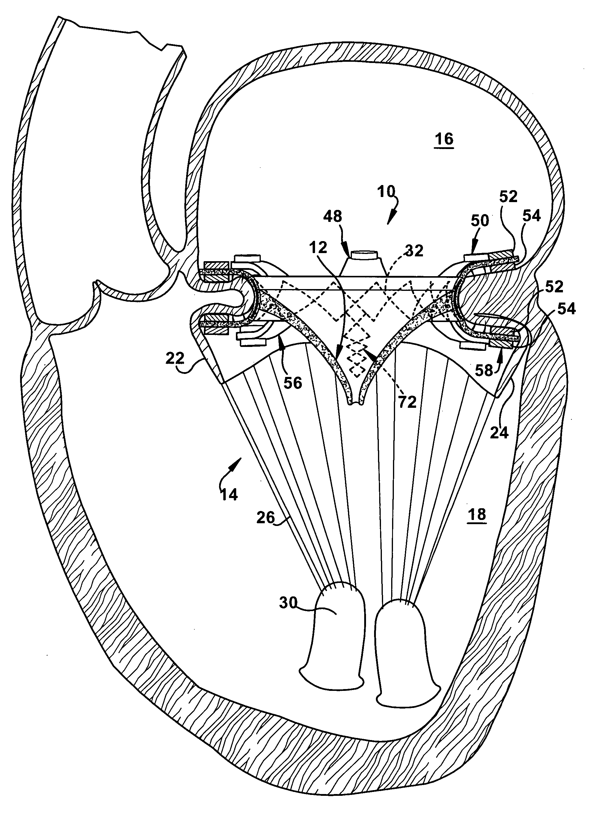
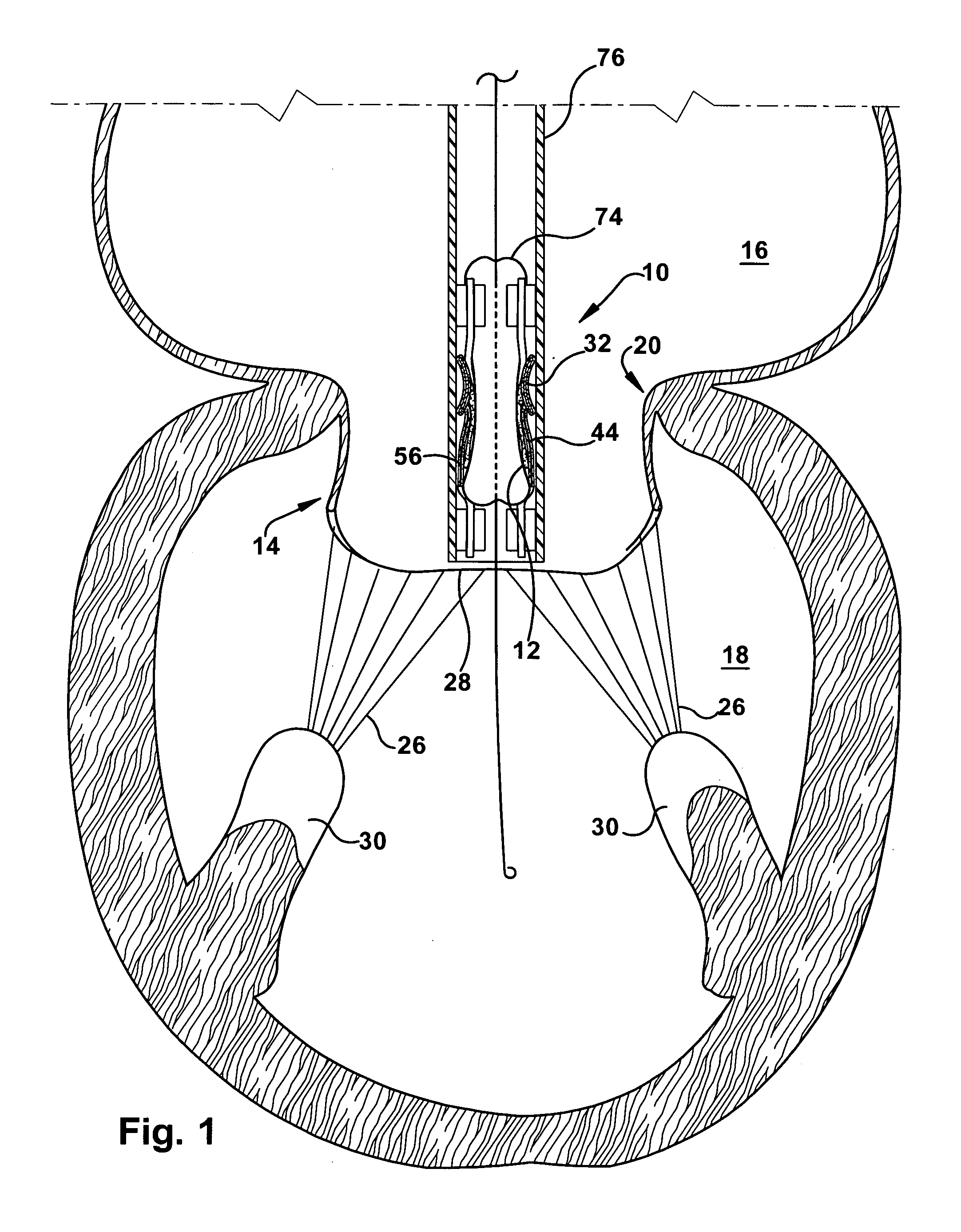
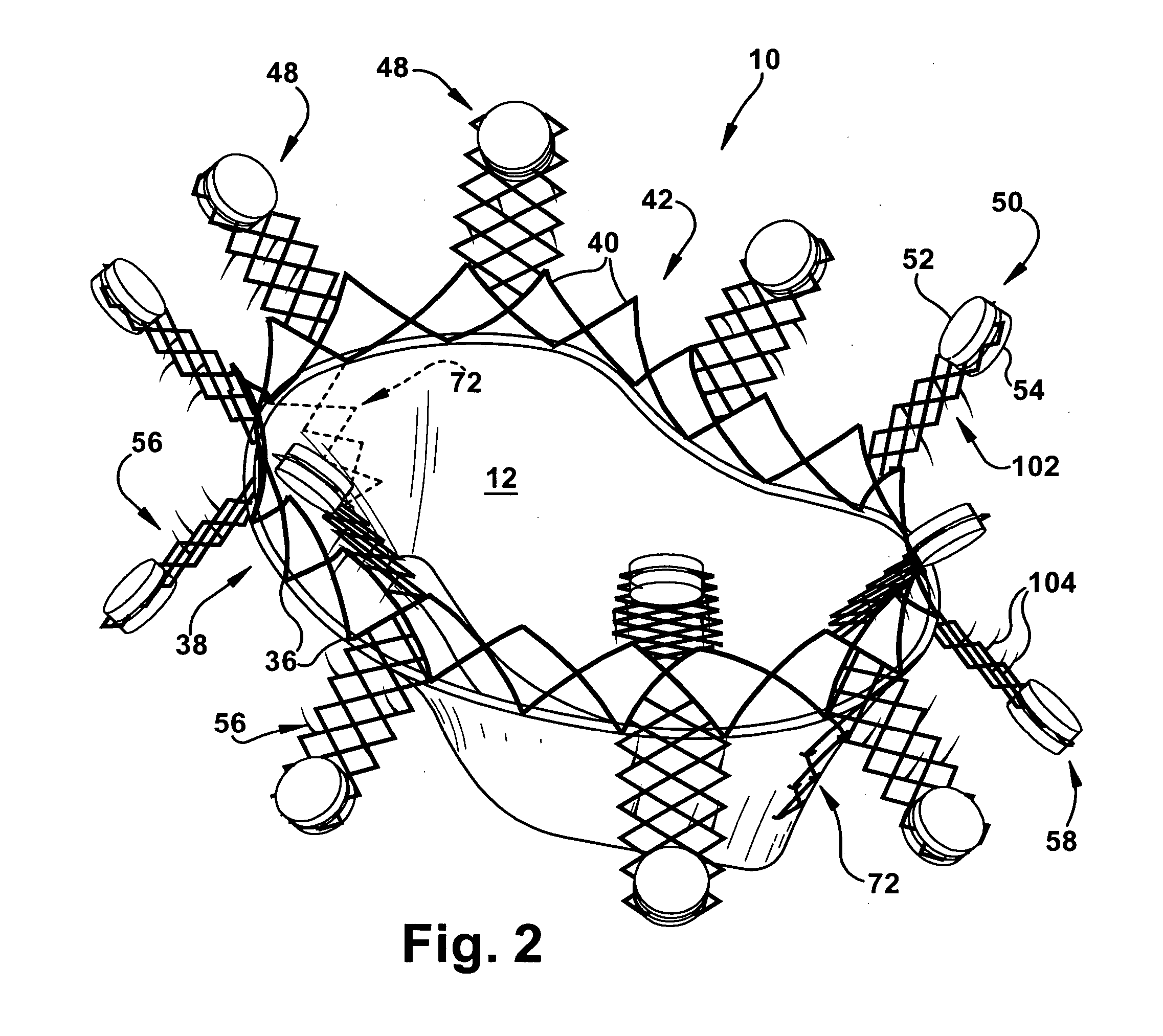
[0034] The present invention relates to an apparatus and method for replacing a cardiac valve, and is particularly directed to an apparatus and method for the correction of mitral valve and tricuspid valve disorders via a minimally invasive, percutaneous approach. As representative of the present invention, FIGS. 1 and 2 illustrate an apparatus 10 that includes a prosthetic valve 12 for replacing a dysfunctional cardiac valve, such as a mitral valve 14, by inserting the apparatus over the native mitral valve so that the prosthetic valve assumes the valvular function. It should be understood, however, that the apparatus 10 disclosed herein could also be used to replace other cardiac valves, such as a tricuspid, pulmonary, or aortic valve.

[0035] As shown in FIG. 1, the mitral valve 14 is located between the left atrium 16 and the left ventricle 18, and functions to prevent backflow of blood from the left ventricle into the left atrium during contraction. The mitral valve 14 has a D-s...


PUM


Abstract

An apparatus for replacing a cardiac valve having at least two native valve leaflets includes an expandable support member with oppositely disposed first and second ends and a main body portion extending between the ends. The first and second ends respectively include a plurality of upper and lower wing members respectively having first and second magnetic components. The wing members extend from the main body portion and are spaced circumferentially thereabout. Secured within the main body portion is a prosthetic valve having at least two valve leaflets. The second end further includes at least two strut members spaced apart from each other and attached to at least one commissural section of the prosthetic valve. The magnetic components are magnetically attracted to one another so that, when the apparatus is placed in the valve annulus, the wing members are pulled toward one another to secure the prosthetic valve in the annulus.

Description

RELATED APPLICATION [0001] This application claims priority from U.S. provisional patent application Ser. No. 60 / 673,056, filed on Apr. 20, 2005, the subject matter of which is incorporated herein by reference.TECHNICAL FIELD [0002] The present invention relates to an apparatus and method for replacing a cardiac valve, and is particularly directed to an apparatus and method for the correction of mitral valve and tricuspid valve disorders via a minimally invasive, percutaneous approach. BACKGROUND OF THE INVENTION [0003] There are two atrioventricular (AV) valves in the heart; one on the left side of the heart and one on the right side of the heart. The left side AV valve is the mitral valve and the right side AV valve is the tricuspid valve. Both of these valves are subject damage and dysfunction that requires that the valve be repaired or replaced. [0004] The mitral and tricuspid valves differ significantly in anatomy. While the annulus of the mitral valve is generally D-shaped, th...

Claims


Application Information

Patent Timeline
IPC IPC(8): A61F2/24
CPCA61B2017/00243A61F2/2409A61F2/2418A61F2/2436A61F2/2457A61F2230/0078A61F2220/0008A61F2220/0016A61F2220/0075A61F2230/005A61F2210/009
Inventor NAVIA, JOSE L.NAVIA, JOSE A.OBERTI, CARLOS
Owner THE CLEVELAND CLINIC FOUND
Why Eureka
Try Eureka