
Microprocessor and control method thereof

a microprocessor and control method technology, applied in the direction of program control, computation using denominational number representation, instruments, etc., can solve the problems of pipeline stall, pipeline stall, pipeline stall,

Inactive Publication Date: 2006-11-16
RENESAS ELECTRONICS CORP
View PDF10 Cites 18 Cited by
  • Summary
  • Abstract
  • Description
  • Claims
  • Application Information

AI Technical Summary

Benefits of technology

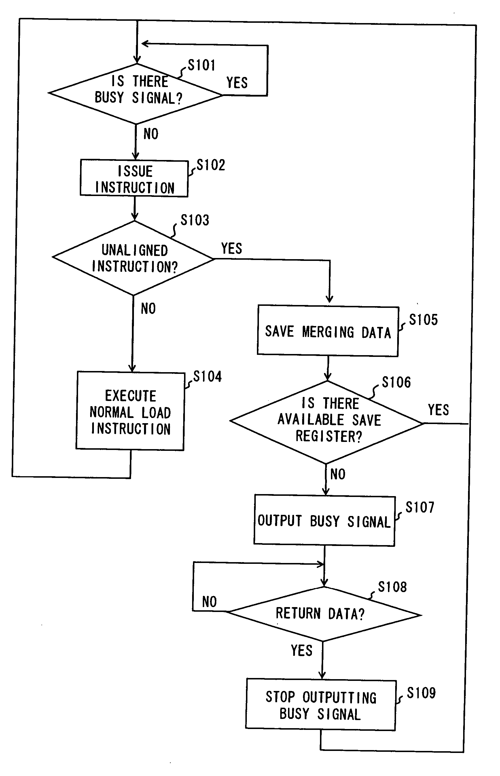
The present invention provides a microprocessor and a control method that can prevent a pipeline stall from occurring when executing an unaligned load instruction. This is achieved by storing the data in a saved register, which allows the microprocessor to use the first input register for subsequent load instructions without generating a resource conflict. This results in a more efficient and effective execution of the unaligned load instruction.

Problems solved by technology

In a microprocessor that performs pipeline process, a cache miss makes a pipeline stall, thereby causing to reduce its performance.
However it has now been discovered that there still is a problem that a pipeline stall can be generated even with a non-blocking load feature if an instruction to be executed is an unaligned load instruction.
The pipeline stall occurs even on a cache hit, not only when an unaligned instruction encounters a cache miss, loading from a main memory, or performing an uncached load.

Method used


Image

  • Microprocessor and control method thereof
  • Microprocessor and control method thereof
  • Microprocessor and control method thereof

Examples


first embodiment

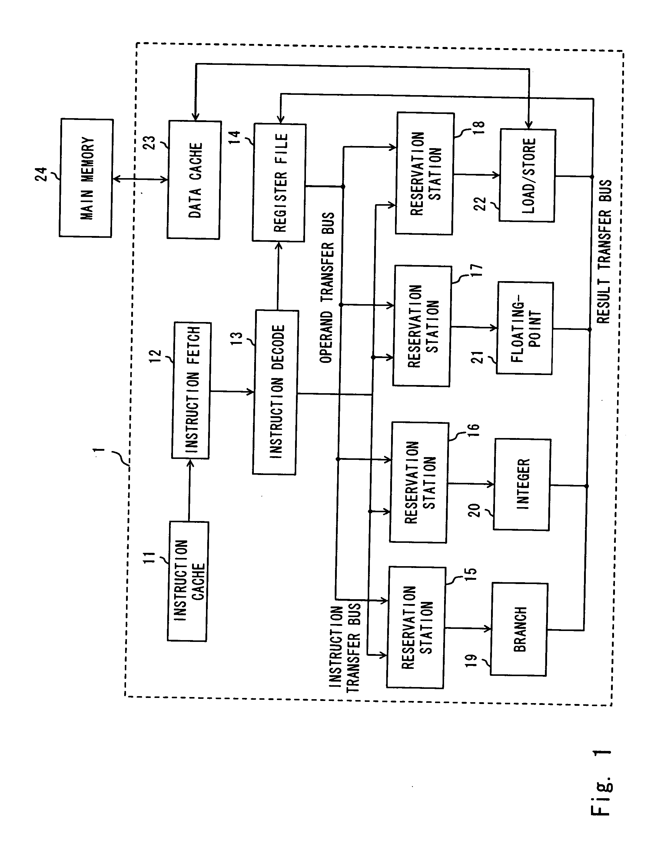
[0043] A configuration of a microprocessor 1 of this embodiment is described hereinafter with reference to FIGS. 1 and 2. FIG. 1 is a view showing an overall configuration of the microprocessor 1. Microprocessor 1 is characterized in that it comprises a load / store unit (LSU) 22 for avoiding a generation of pipeline stall in case of a cache miss occurred while executing an unaligned load instruction. In FIG. 1, constituents other than the load / store unit 22 are identical to the constituents of the microprocessor 8 shown in FIG. 8, accordingly they are denoted by reference numerals identical to those therein with detailed description omitted.

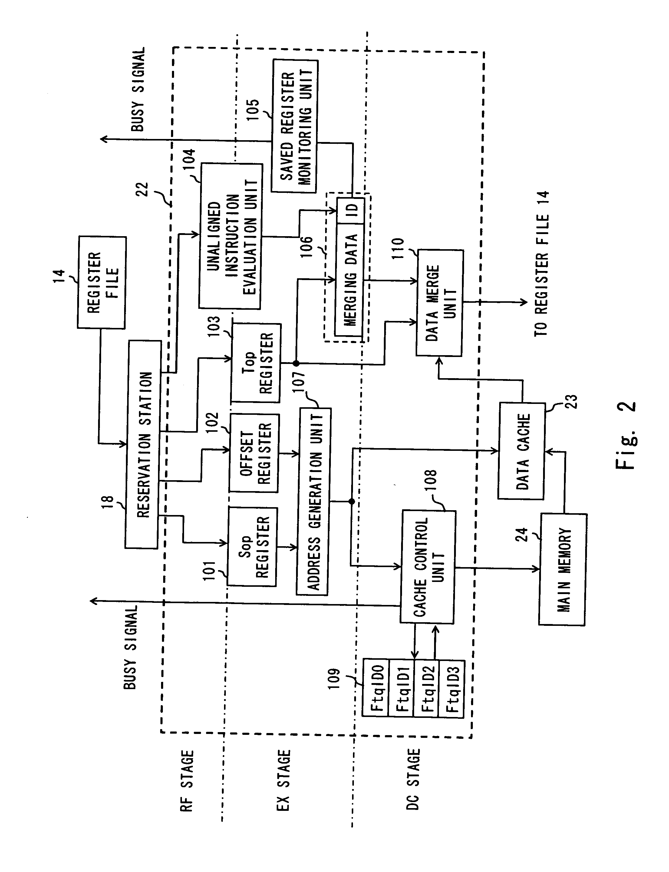
[0044]FIG. 2 is a view showing a configuration of the LSU 22 included in the microprocessor 1. The LSU 22 includes a saved register 106 and a saved register monitoring unit 105. When a unaligned instruction evaluation unit 104 acknowledges that an unaligned load instruction is issued, a merging data set to the Top register 103 is stored to the sa...

second embodiment

[0054] A difference of a microprocessor of this embodiment from the microprocessor 1 of the previous embodiment is that a saved register to store merging data is made capable of storing merging data at least for the number of instructions that are saved in the fetch queue 109.

[0055] A configuration of LSU 32 included in the microprocessor of this embodiment is shown in FIG. 5. In FIG. 5, constituents other than the LSU32 are identical to the constituents of the microprocessor 1 of the first embodiment, accordingly a drawing to show an overall configuration of a microprocessor and its descriptions are omitted.

[0056] The saved register 206 included in the LSU 32 is capable of storing merging data for the same number the fetch queue 109 can save. In FIG. 5, the number of storable merging data is for 4 instructions.

[0057] Such a configuration enables the saved register 206 to save merging data even in a case when as many unaligned load instructions as storable in a fetch queue are is...


PUM


Abstract

A load / store unit includes a Top register for storing a value retained before loading to a load destination register and a saved register capable of storing data retained to the Top register. When an unaligned instruction evaluation unit determines that a load instruction issued from a instruction decode unit is an unaligned instruction, data stored to the Top register are stored to the saved register in order to make the Top register available to subsequent load instructions issued from the instruction decode unit.

Description

BACKGROUND OF THE INVENTION [0001] 1. Field of the Invention [0002] The present invention relates to an architecture of a microprocessor, and particularly to a microprocessor provided with a non-blocking load feature. [0003] 2. Description of Related Art [0004] One of primary objects for microprocessor developers is to improve instruction processing speed of a microprocessor. Using cache memory is well known as a technique to improve processing speed of a microprocessor. The cache memory is used to eliminate a difference between processing speed of a microprocessor and data transfer rate of a main memory such as DRAM. [0005] However if data to be used in an operation is not stored in a cache memory, data must be transferred from a low-speed main memory that resides outside a processor. Where data to be used in a microprocessor does not exist in a cache memory on a cache access, it is referred to as a “miss hit” or a “cache miss”. When a cache miss occurs, the cache memory cannot be ...

Claims


Application Information

Patent Timeline
Patent Type & Authority Applications(United States)
IPC IPC(8): G06F9/44
CPCG06F9/30032G06F9/3867G06F9/30043
Inventor KUNIE, SHUICHI
Owner RENESAS ELECTRONICS CORP
Learn More