
Programmatically Generating a Graphical Program in Response to User Input

a program and user input technology, applied in the field of graphical programming, can solve the problems of difficult for instrumentation application developers to properly implement code to analyze an acquired signal, and achieve the effect of simplifying the user's task of implementing various and easily specifying the desired functionality

Inactive Publication Date: 2006-11-16
NATIONAL INSTRUMENTS
View PDF36 Cites 46 Cited by
  • Summary
  • Abstract
  • Description
  • Claims
  • Application Information

AI Technical Summary

Benefits of technology

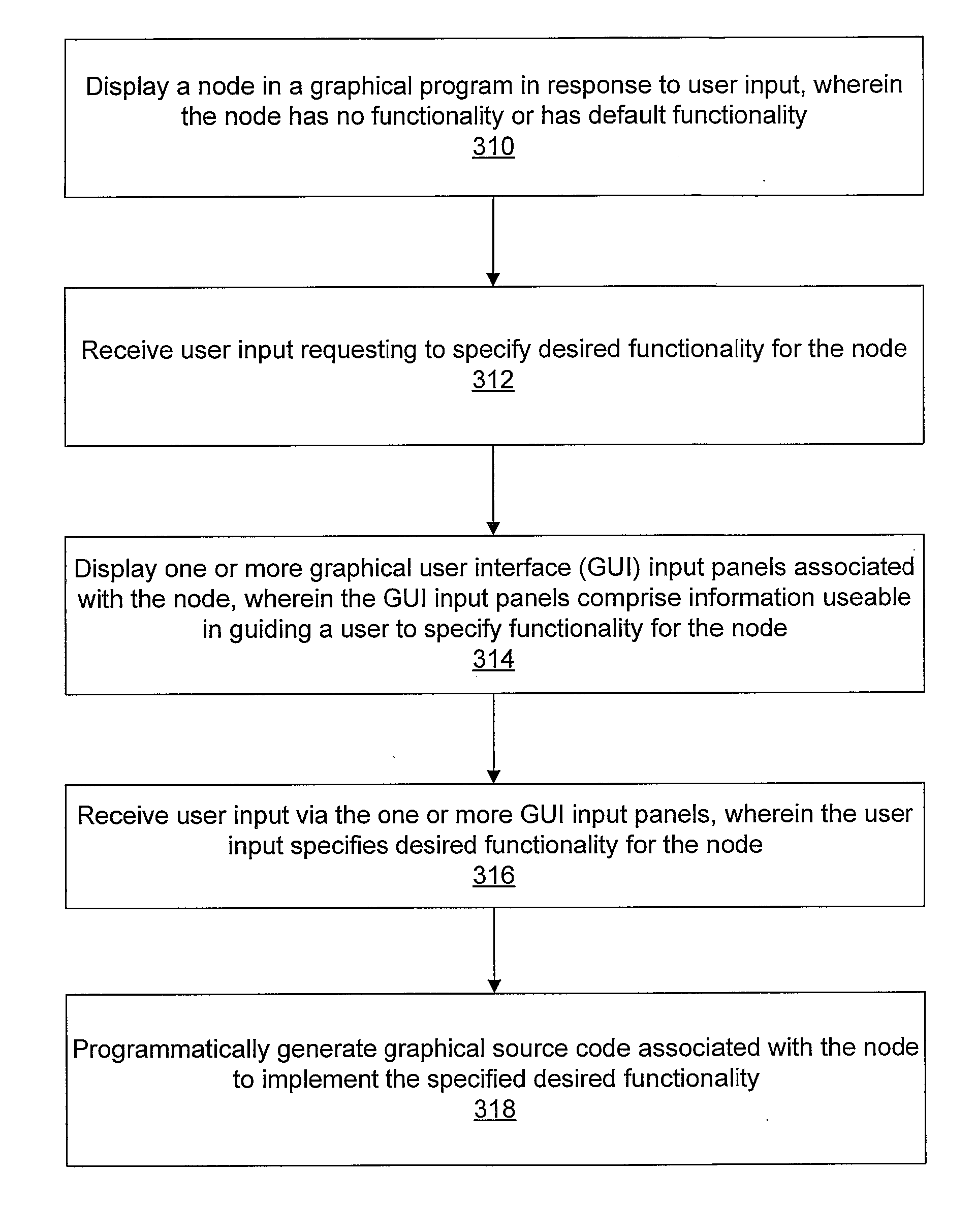
[0021] Also, the GPG program may have any of various purposes or applications. In one embodiment, the GPG program may include or be associated with a program or application that directly aids the user in creating a graphical program. For example, the GPG program may be included in a graphical programming development environment application. In this case the graphical programming development environment application may be operable to receive user input specifying desired functionality and the GPG program may automatically, i.e., programmatically, add a portion of graphical program code implementing the specified functionality to the user's program. The user input may be received, for example, via one or more “wizardgraphical user interface (GUI) input panels or dialogs enabling the user to specify various options. Such graphical program code generation wizards may greatly simplify the user's task of implementing various operations. As an example, it is often difficult for developers of instrumentation applications to properly implement code to analyze an acquired signal, due to the inherent complexity involved. By enabling the developer to easily specify the desired functionality through a high-level user interface, the GPG program can receive this information and automatically create graphical code to implement the signal analysis. Furthermore, since the graphical code is generated programmatically, the code may be optimized, resulting in an efficient program and a readable block diagram without unnecessary code.

Problems solved by technology

As an example, it is often difficult for developers of instrumentation applications to properly implement code to analyze an acquired signal, due to the inherent complexity involved.

Method used


Image

  • Programmatically Generating a Graphical Program in Response to User Input
  • Programmatically Generating a Graphical Program in Response to User Input
  • Programmatically Generating a Graphical Program in Response to User Input

Examples


Embodiment Construction

Incorporation by Reference

[0050] The following references are hereby incorporated by reference in their entirety as though fully and completely set forth herein.

[0051] U.S. Pat. No. 5,481,741 titled “Method and Apparatus for Providing Attribute Nodes in a Graphical Data Flow Environment,” issued on Jan. 2, 1996.

[0052] U.S. Pat. No. 6,064,812 titled “System and Method for Developing Automation Clients Using a Graphical Data Flow Program,” issued on May 16, 2000.

[0053] U.S. Pat. No. 6,102,965 titled “System and Method for Providing Client / Server Access to Graphical Programs,” issued on Aug. 15, 2000.

[0054] U.S. patent application Ser. No. 09 / 136,123 titled “System and Method for Accessing Object Capabilities in a Graphical Program” filed Aug. 18, 1998.

[0055] U.S. patent application Ser. No. 09 / 518,492 titled “System and Method for Programmatically Creating a Graphical Program”, filed Mar. 3, 2000.

[0056] U.S. patent application Ser. No. 09 / 595,003 titled “System and Method for A...


PUM


Abstract

A system and method for programmatically generating a graphical program or a portion of a graphical program in response to receiving user input. The user input may specify functionality of the graphical program or graphical program portion to be generated. In response to the user input, a graphical program (or graphical program portion) that implements the specified functionality may be programmatically generated. Thus, different graphical programs may be generated, depending on the user input received.

Description

PRIORITY CLAIM [0001] This application is a continuation of U.S. patent application Ser. No. 09 / 886,455 titled, “System and Method for Programmatically Generating a Graphical Program in Response to User Input”, filed Jun. 20, 2001, whose inventors were Jeffrey D. Washington, Ram Kudukoli, Robert E. Dye, and Paul F. Austin, which is a continuation-in-part of and claims priority to U.S. patent application Ser. No. 09 / 745,023 titled, “System and Method for Programmatically Generating a Graphical Program in Response to Program Information,” filed Dec. 20, 2000, whose inventors were Ram Kudukoli, Robert Dye, Paul F. Austin, Lothar Wenzel and Jeffrey L. Kodosky, which claims benefit of priority of U.S. patent application Ser. No. 09 / 518,492 titled “System and Method for Programmatically Creating a Graphical Program”, filed Mar. 3, 2000, whose inventors were Ram Kudukoli, Robert Dye, Melanie Jensen, and Yumiko Kawachi, which claims benefit of priority of U.S. provisional Patent Application...

Claims


Application Information

Patent Timeline
Patent Type & Authority Applications(United States)
IPC IPC(8): G06F9/44
CPCG06F8/34
Inventor WASHINGTON, JEFFREY D.KUDUKOLI, RAMDYE, ROBERT E.AUSTIN, PAUL F.
Owner NATIONAL INSTRUMENTS
Learn More