Method for riveting fins into bottom plate of heat dissipating device

Inactive Publication Date: 2006-11-23
CHEN SHYH MING
View PDF4 Cites 0 Cited by
  • Summary
  • Abstract
  • Description
  • Claims
  • Application Information

AI Technical Summary

Benefits of technology

[0004] Accordingly, the primary object of the present invention is to provide a method for riveting fins into a bottom plate of a heat dissipating device. The present invention can be used for high level electronic device or IC circuits. Further more fins can be embedded in a seat so as to increase the heat dissipating area. Moreover in the process of the present invention, the punching force is uniformly distributed on the seat so that the fins can be densely arranged to provide a high efficiency heat dissipation function.

Problems solved by technology

Moreover, the fins 14 have errors so that the weights 13 cannot be accurately aligned to the gaps between fins 14.
As a result, in the punching process, it is possible that the fins 14 will be destroyed and thus the yield ratio is low.
However the weights 13 are expensive.

Method used


Image

  • Method for riveting fins into bottom plate of heat dissipating device
  • Method for riveting fins into bottom plate of heat dissipating device
  • Method for riveting fins into bottom plate of heat dissipating device

Examples


Embodiment Construction

[0014] In order that those skilled in the art can further understand the present invention, a description will be provided in the following in details. However, these descriptions and the appended drawings are only used to cause those skilled in the art to understand the objects, features, and characteristics of the present invention, but not to be used to confine the scope and spirit of the present invention defined in the appended claims.

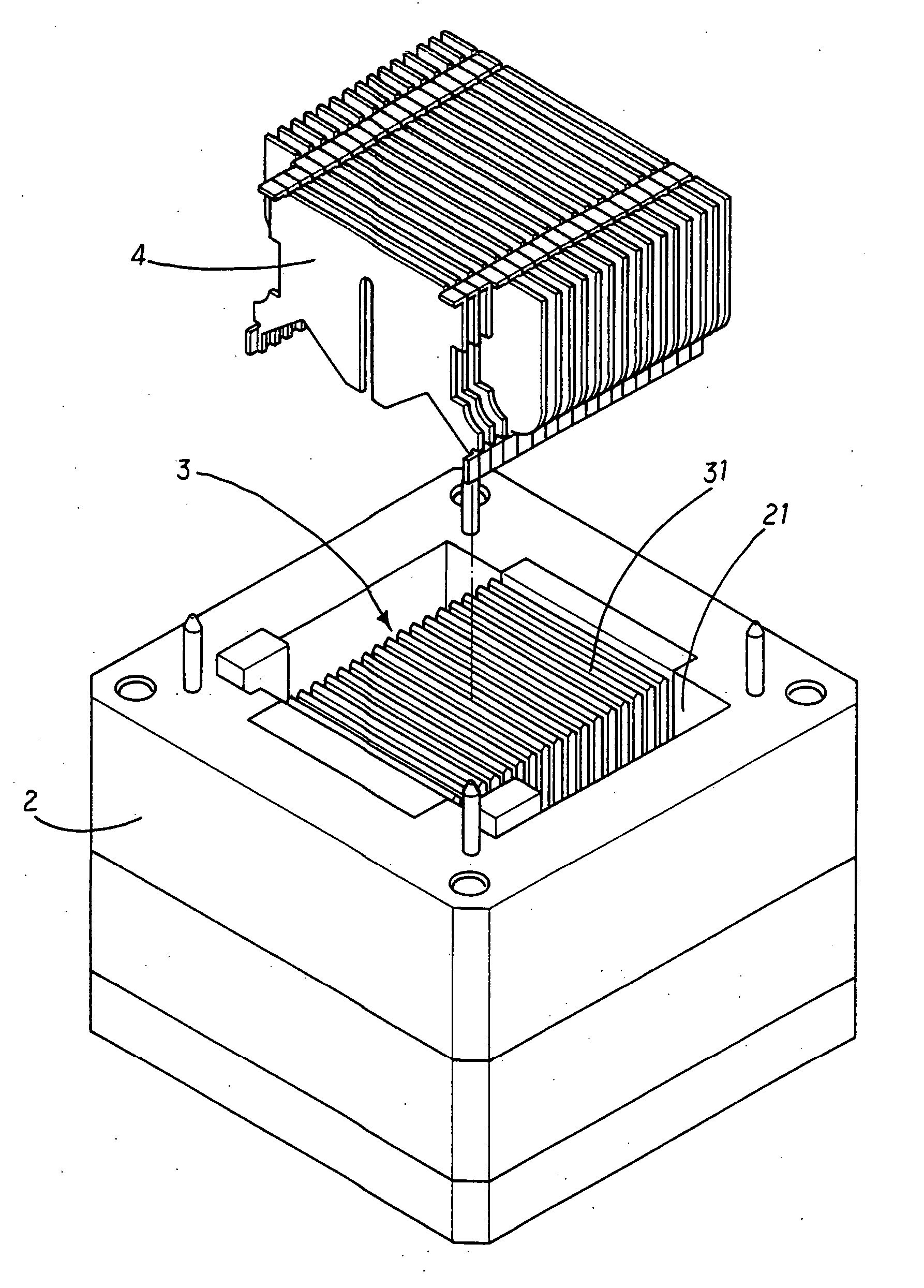
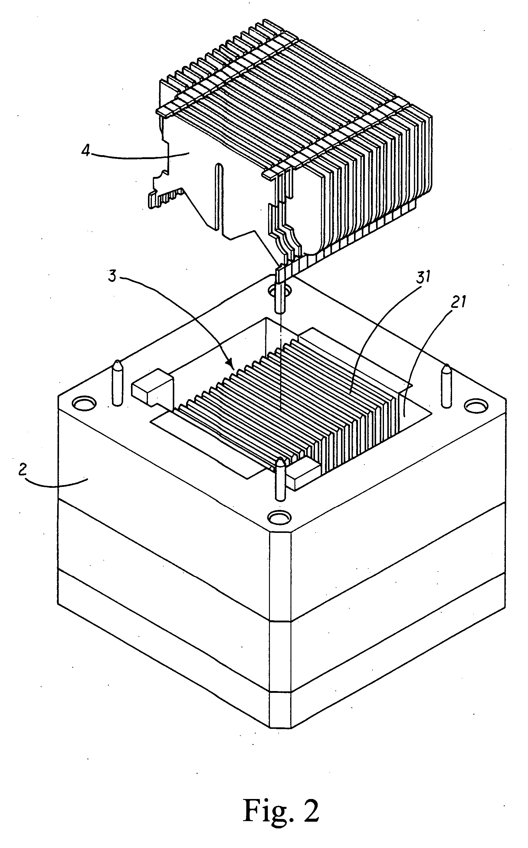
[0015] With reference to FIGS. 2 and 3, the present invention has the following elements.

[0016] A fixture 2 has a recess 21.

[0017] A punching device 3 has a plurality of weights 31 each of which is formed as a thin sheet. The punching device 3 is installed in the recess 21 of the fixture 2.

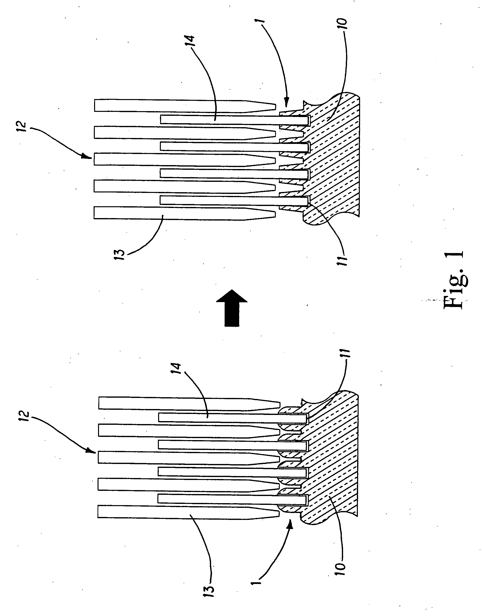
[0018] A plurality of fins 4 are spaced with a predetermined gap.

[0019] A bottom plate 5 is formed with a plurality of trenches 51 for receiving the fins 4.

[0020] In the manufacturing process, the bottom plate 5 is positioned at the fixture 2. The fins 4 a...


PUM

PropertyMeasurementUnit
Weightaaaaaaaaaa
Forceaaaaaaaaaa

Abstract

A method for riveting fins into a bottom plate of a heat dissipating device is disclosed. A punching device has a plurality of weights each of which is formed as a thin sheet. The punching device is installed to a fixture; a plurality of fins are spaced with a predetermined gap; and a bottom plate is formed with a plurality of trenches for receiving the fins. The method comprising the step of: positioning the bottom plate at the fixture; inserting the fins into the trenches of the bottom plate; inserting the weights of the punching device into the fins so that each space between two fins has a weight; and punching a backside of the bottom plate by a puncher so that as the bottom plate moves; the weights collides portions of the bottom plate between the fins to deform and rivet the fins into the bottom plate; and thus the fins are firmly secured in the bottom plate.

Description

FIELD OF THE INVENTION [0001] The present invention relates to heat dissipation, and in particular to a method for riveting fins into a bottom plate of a heat dissipating device. The present invention can be used for high-level electronic device or IC circuits. Further more fins can be embedded in a seat so as to increase the heat dissipating area. Moreover in the process of the present invention, the punching force is uniformly distributed on the seat so that the fins can be densely arranged to provide high efficiency heat dissipation function. BACKGROUND OF THE INVENTION [0002] In the current integrated circuit (IC) or electronic devices, the heat dissipating device has a bottom plate and a heat dissipating unit. The bottom plate has a plurality of trenches. Fins are inserted into the trenches. The method for fixing the fins to the bottom plate can be referred to FIG. 1. The bottom plate 10 of the heat dissipating device 1 is formed with trenches 11. The bottom plate 10 is fixed t...

Claims


Application Information

Patent Timeline
IPC IPC(8): B21D53/02
CPCB21D53/02Y10T29/49908Y10T29/4935Y10T29/49366Y10T29/49915
Inventor CHEN, SHYH-MING
Owner CHEN SHYH MING
Why Eureka
Try Eureka