LED lamp heat dissipation structure with outward corrugations and reflector function

Pending Publication Date: 2022-10-06
LIN CHIEN TING
View PDF3 Cites 0 Cited by
  • Summary
  • Abstract
  • Description
  • Claims
  • Application Information

AI Technical Summary

Benefits of technology

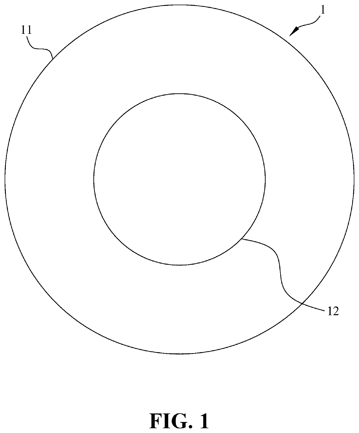
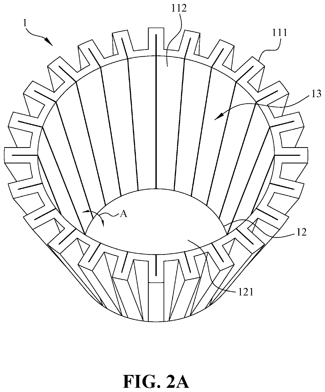
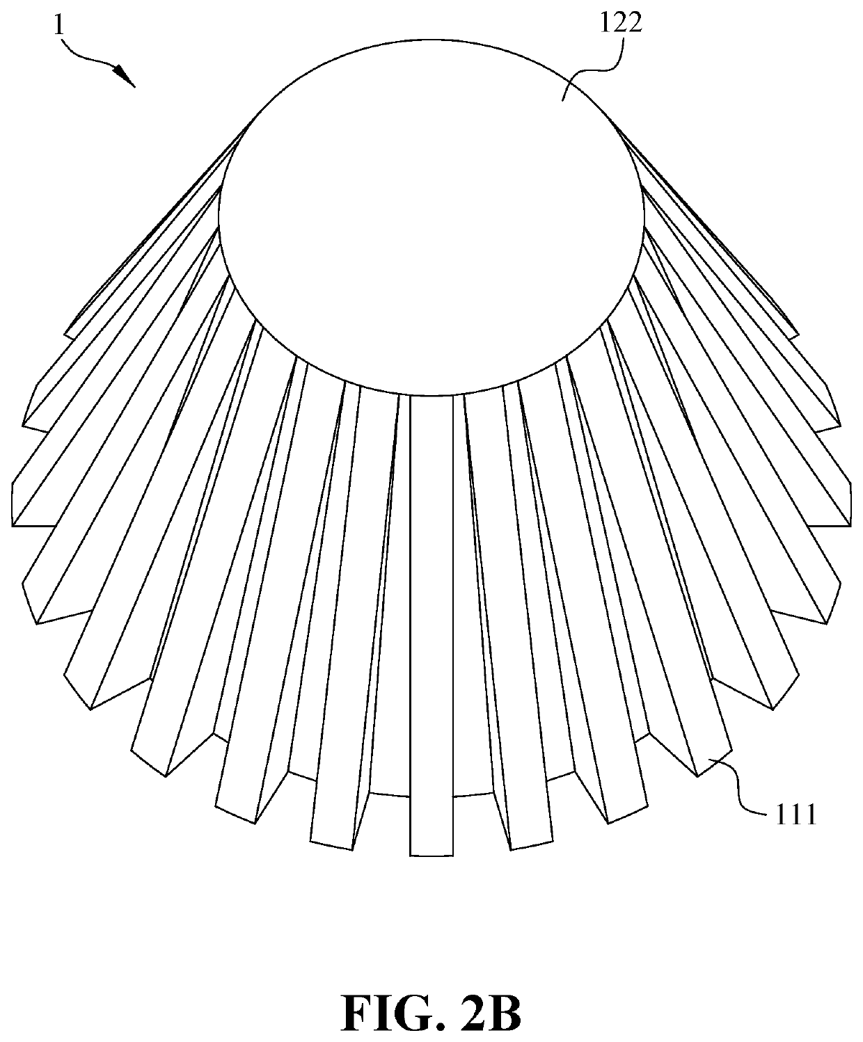
The present invention provides an LED lamp heat dissipation structure with outward corrugations and a reflector function, which can achieve lower energy consumption and solve the problems of poor heat dissipation and low heat conduction efficiency for the existing LED lamp heat dissipation structures. The tapered portion can have a reflection effect, and the outward corrugations can increase the heat dissipation area. The tapered portion is provided with a light guide cover at an opening edge thereof so as to make the light more uniform.

Problems solved by technology

The casting method has the advantages of integrally formed structure and good heat conduction effect, but has the disadvantages of high production cost and too many subsequent machining processes.
The thickness of the radiator will be limited by the production method.
As such, it cannot be manufactured to be too thin, and the actual heat dissipation effect will also be affected.
The disadvantage is that such products are made up of various stamping parts, which will affect the heat conduction effect.

Method used


Image

  • LED lamp heat dissipation structure with outward corrugations and reflector function
  • LED lamp heat dissipation structure with outward corrugations and reflector function
  • LED lamp heat dissipation structure with outward corrugations and reflector function

Examples


embodiment 1

[0034]As shown in FIG. 4, in Embodiment 1 of the present invention, the arrows show the conduction path of the heat 3. In fact, most of the heat 3 is evenly conducted from the second predetermined shape portion 12 to the ambient air C through the tapered portion 112 and the outward corrugations 111, but is not limited to the direction of the arrows in FIG. 4.

[0035]As shown in FIGS. 5A to 5C especially in FIG. 5B, in Embodiment 1 of the present invention, a part of the light 4 directly irradiates outward, and the other part of the light 4 irradiates the tapered portion 112 and then is reflected outward. To more clearly illustrate the reflection effect of the tapered portion 112, as shown in FIG. 5C, the light emitted from the LED lamp substrate 2 is simplified into a first luminous point 21 and a second luminous point 22, all of the light 4 directly irradiated outward from the first luminous point 21 and the second luminous point 22 are omitted, and only three reflected light beams 4...

embodiment 2

[0036]FIGS. 6A to 8B show Embodiment 2 and Embodiment 3 of the present invention. As shown in FIGS. 6A to 7B, the second predetermined shape portion 12 is formed to have a convex platform 1211 protruded toward the inner space 13, and the outer surface 122 is formed to have a corresponding recess 1221 with a flat bottom. The tapered portion 112 are uniformly cut at predetermined places to form a plurality of U-shaped pieces 1121, each of the plurality of U-shaped pieces 1121 is located between two adjacent outward corrugations 111, and a bottom of each of the plurality of U-shaped pieces 1121 faces the second predetermined shape portion 12. As shown in FIGS. 6C and 6D, each of the plurality of U-shaped pieces 1121 is respectively bent toward the inner space 13 to be connected with the convex platform 1211, and a plurality of heat dissipation holes 1122 are respectively formed in original positions of the plurality of U-shaped pieces 1121 before being bent. In Embodiment 2 and Embodim...

embodiment 3

[0038]FIGS. 7A and 7B show Embodiment 3 of the present invention. The second predetermined shape portion 12 is stretched toward the inner space 13 to form the recess 1221 and the convex platform 1211, and the recess 1221 is surrounded by a stretched surface without corrugations.

[0039]Preferably, as shown in FIG. 6D, each of the plurality of U-shaped pieces 1121 is respectively bent toward the inner space 13 to be connected to the convex platform 1211. In order to prevent the U-shaped pieces 1121 from being bent and concentrated to a center of the convex platform 1211, a small convex platform 1212 can be provided in the center of the convex platform 1211 to compensate for a gap therebetween, so that the LED lamp substrate 2 is in full contact with the convex platform 1211 and the U-shaped pieces 1121, thereby increasing the heat conduction effect.

[0040]Preferably, the U-shaped pieces 1121 of Embodiment 2 and Embodiment 3 can be respectively bent toward the inner space 13 to an edge o...


PUM


Abstract

Provided is an LED lamp heat dissipation structure, including: a metal plate and an LED lamp substrate. The metal plate has a first predetermined shape portion, wherein a center of the metal plate is defined to have a second predetermined shape portion, an outer edge of the metal plate is formed to be a tapered portion with outward corrugations and with a center at the second predetermined shape portion, the tapered portion has a predetermined inclination angle with respect to the second predetermined shape portion, two surfaces of the second predetermined are defined as an inner surface and an outer surface, respectively, and the tapered portion surrounds the inner surface to define an inner space. The LED lamp substrate is closely attached to the inner surface. The heat generated from the LED lamp substrate can be efficiently transferred to an ambient air through the LED lamp heat dissipation structure.

Description

BACKGROUND OF THE INVENTION1. Field of the Invention[0001]The present invention relates to an LED lamp heat dissipation structure, and more particularly to an LED lamp heat dissipation structure with outward corrugations and a reflector function.2. The Prior Art[0002]The existing LED lamp heat dissipation structures are generally formed by mold casting a metal with excellent heat conductivity, such as aluminum die-casting radiator. The casting method has the advantages of integrally formed structure and good heat conduction effect, but has the disadvantages of high production cost and too many subsequent machining processes. The thickness of the radiator will be limited by the production method. As such, it cannot be manufactured to be too thin, and the actual heat dissipation effect will also be affected.[0003]Another existing LED lamp heat dissipation structures are formed by stamping a thin metal sheet with excellent heat conductivity. The stamping method has the advantage that t...

Claims


Application Information

Patent Timeline
IPC IPC(8): F21V29/77
CPCF21V29/773F21Y2115/10F21V29/505F21K9/232
Inventor LIN, CHIEN-TING
Owner LIN CHIEN TING
Why Eureka
Try Eureka